110 PWR-01
Parallel/ Series Operation | Series operation
Connection
Connecting the Load
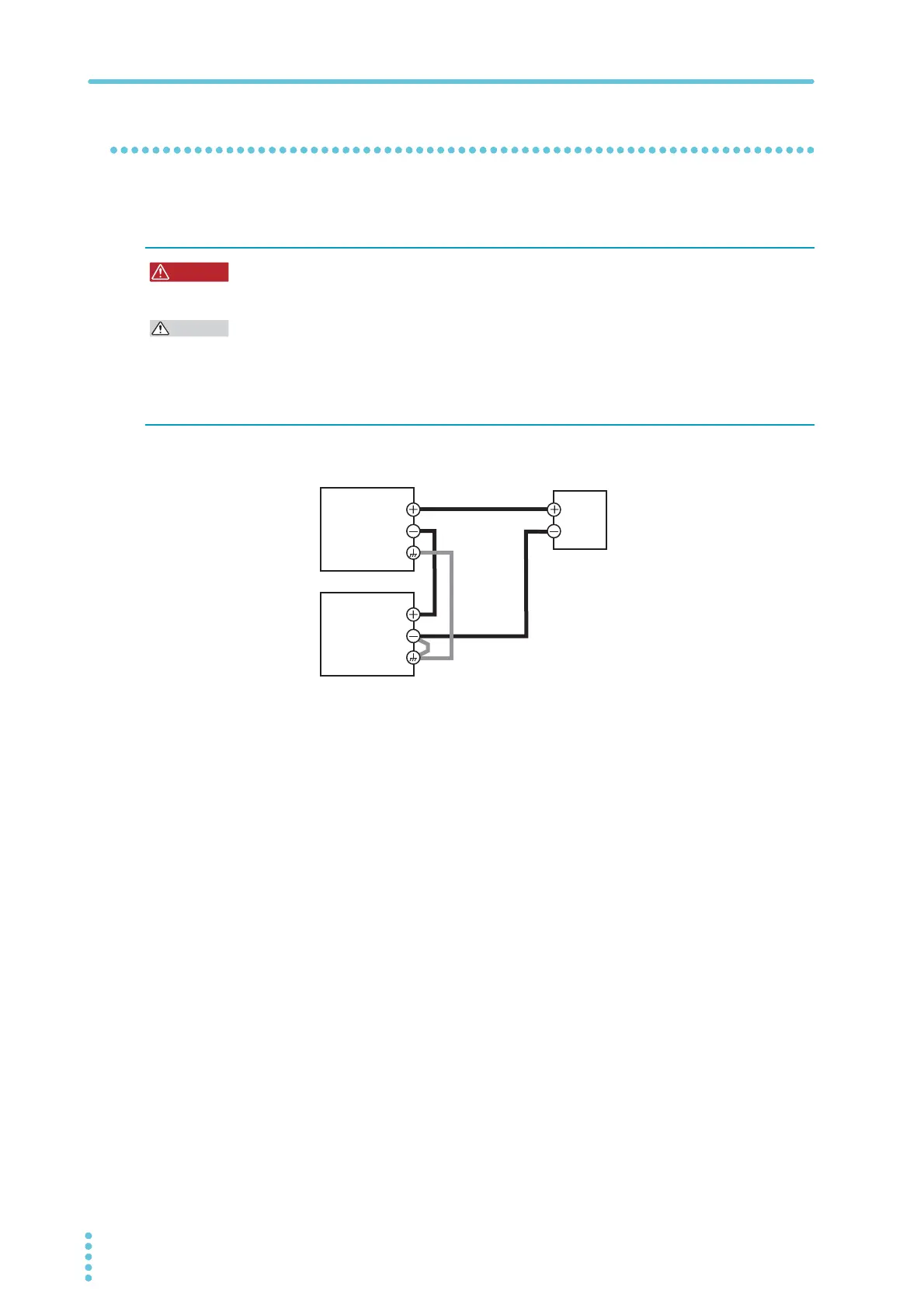
Connect the load as shown below.
1
Turn off all the PWR-01s that you want to connect in series.
2
Remove the OUTPUT terminal covers.
3
Connect the output terminal (positive or negative) of unit 1 or unit 2 to
the chassis terminal.
4
Use load cables to connect unit 1 and unit 2 to the load or relay terminal
block.
Use load cables that have sufficient current capacity (p.20). Wire the load cables so
that they are as short as possible. If the voltage drop in the load cable is large, the dif-
ference in electric potential between power supply units and the load regulation
become large.
5
Connect the cables to the output terminals of unit 1 and unit 2.
6
Attach the OUTPUT terminal cover.
Risk of electric shock. Turn the POWER switch off before you touch the output termi-
nals. Attach the OUTPUT terminal cover after you finish wiring the load.
To prevent oscillation, connect an electrolytic capacitor with a capacitance of a few hundred
µF to a few ten thousand µF across the load as necessary. If the wires are long, the wiring
inductance and capacitance can cause phase shifting at a level that can not be ignored. This
may lead to oscillation.
The withstand voltage of the electrolytic capacitor needs to be at least 120 % of the total
rated output voltage of the PWR-01s connected in series.
Load or relay terminal block
Output terminal
Chassis terminal
Output terminal
Chassis terminal
Load connection in series operation
(In this example, the negative terminal of unit 2
is connected to the chassis terminal.)