90 PWR-01
Output voltage control
This section explains how to control the output voltage using an external voltage (Vext) or an
external variable resistor (Rext) of approximately 10 kΩ.
If no load is connected, it takes some time for the output voltage to decrease.
Control using an external voltage (Vext)
To use an external voltage (Vext) to control the output voltage, set CV control using an exter-
nal voltage or external resistance to on (CF11: ON) in CONFIG settings.
The output voltage (Eo) varies in the range of 0 to the rated output voltage (Ertg) when the
external voltage (Vext) is changed in the range of 0 V to 5 V (CF12: LO) or in the range of 0 V
to 10 V (CF12: HI).
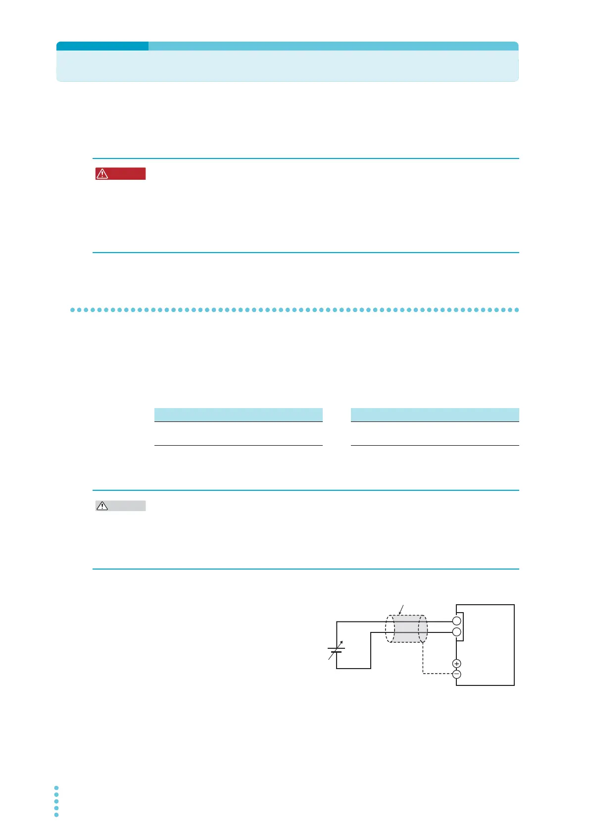
External voltage (Vext) connection
Use a low-noise, stable voltage source
for Vext. The noise in Vext is multiplied
by the amplification factor of the PWR-
01 and appears in the output. There-
fore, the output ripple noise may not
meet the specifications of the PWR-01.
To reduce the influence of noise on the
output, connect a 2-core shielded wire
or a twisted-pair wire across Vext, and
keep the wire as short as possible. If
the wiring between the PWR-01 and
the external contact is long, it becomes easy for noise to influence the operation of the PWR-
01. Even if you use cables that are designed to suppress noise, the PWR-01 may not operate
properly.
Risk of electric shock.
• Ensure that the insulation of Vext or Rext and the connected cable is greater than or
equal to the isolation voltage of the PWR-01. For details on the isolation voltage of
each model, see Chap.7 "Specifications" (p.117).
• When using shielded cables for the connection, protect the uncovered sections of
the shielded cable by using insulation tubes whose withstand voltage is greater than
the PWR-01’s isolation voltage.
External voltage (Vext) 0 V to 5 V (CF12: LO) External voltage (Vext) 0 V to 10 V (CF12: HI)
Eo = Ertg×Vext /5 [V]
Vext = 5×Eo /Ertg [V]
Eo = Ertg×Vext /10 [V]
Vext = 10×Eo /Ertg [V]
• The signal cable may burn out. Do not connect the Vext output, that is, leave it floating.
Risk of damage.
• Pay careful attention to the polarity of Vext.
• Do not apply a voltage of 10.5 V or greater or a reverse voltage across pins 1 and 5 of the
J1 connector.
2-core shielded wire or
Vext
+
–
Output terminal
J1
1
5
PWR-01