PWR-01 23
Installation and Preparation | Output Terminal Insulation
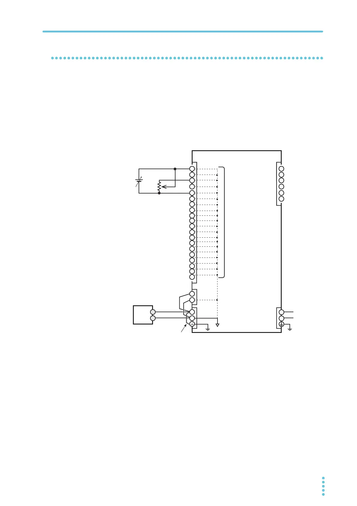
When the output terminal is grounded
If the positive output terminal is connected to the chassis terminal, the positive output termi-
nal is at ground potential. The cable and load that are connected to the output terminal
(including the sensing terminal) will only require an insulation capacity that is greater than or
equal to the maximum output voltage of the PWR-01 with respect to the chassis.
The same holds true when the negative terminal is connected to the chassis terminal. The
cable and load require an insulation capacity that is greater than or equal to the maximum
output voltage of the PWR-01.
For safety reasons, connect one of the output terminals to the chassis terminal unless your
application requires the output terminals to be floating.
+
–
+
+S
–S
–
+
–
16
17
18
19
14
15
20
2
3
4
5
6
13
12
11
10
9
8
7
1
2
3
4
5
6
1
AC
DC
OUTPUT
J1 J2
SENS
L
N
Load
Rext
PWR-01
Vext
Chassis terminal
Approximately the
same electric potential
as the negative output
terminal
All pins of the J1 connector are
at approximately the same elec-
tric potential as the PWR-01’s
negative output terminal.