PWR-01 97
Controlling the Clearing of Alarms
This section explains how to use an external contact to clear alarms.
To reduce the influence of noise on the output, connect a 2-core shielded wire or a twisted-
pair wire across the external contact, and keep the wire as short as possible. If the wiring is
long, it becomes easy for noise to influence the operation of the PWR-01. Even if you use
cables that are designed to suppress noise, the PWR-01 may not operate properly.
If you use a shielded cable, connect the shield to the negative output terminal.
Alarms are cleared when a low (0 V to 0.5 V) signal is applied to pin 6 of the J1 connector or
the pin is shorted.
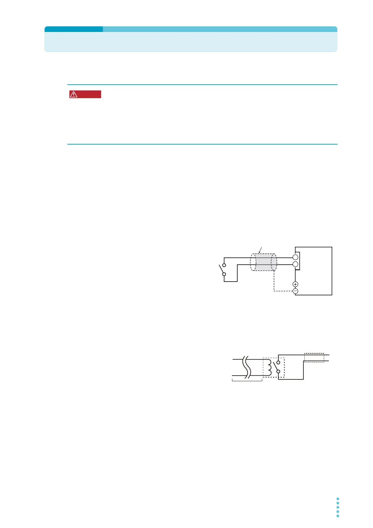
Alarm clear connection
Use pins 5 and 6 of the J1 connector.
The open-circuit voltage across pins 5
and 6 is approximately 5 V. The short-
circuit current across pins 5 and 19 is
approximately 0.5 mA.
Use external contacts that have a con-
tact rating greater than or equal to
0.5 mA at 5 Vdc.
If two or more units are floating, and you are using a single external contact to clear alarms,
use a relay or similar device for the external contact signal to isolate the signal transmitted to
each unit.
For long-distance wiring
When you are wiring over a great distance,
use a small relay and extend the coil side of
the relay.
Risk of electric shock.
• Ensure that the insulation of external contact (S) and the connected cable is greater
than or equal to the isolation voltage of the PWR-01. For details on the isolation volt-
age of each model, see Chap.7 "Specifications" (p.117).
• When using shielded cables for the connection, protect the uncovered sections of
the shielded cable by using insulation tubes whose withstand voltage is greater than
the PWR-01’s isolation voltage.
twisted pair wires
Output terminal
J1
6
5
PWR-01
Switch