88 PWR-01
Notes for Connecting External Voltage (Vext)
This section contains notes for controlling the output using external voltage (Vext).
A GND terminal
The electric potential of A GND (J1-5, J1-10, and J1-15) of the J1 connector that Vext is con-
nected to varies depending on whether remote sensing is used.
• When remote sensing is not used: Same electric potential as the negative output
terminal
• When remote sensing is used: Same electric potential as the negative electrode (-S) of
sensing input
Floating
When using shielded cables
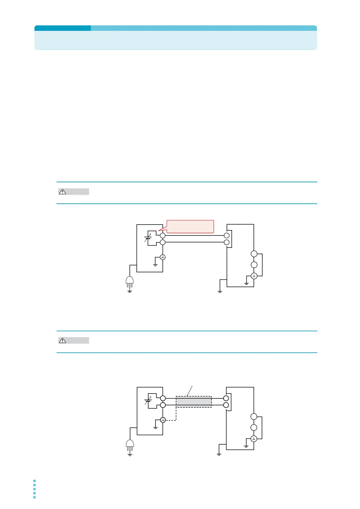
When using shielded cables, connect the shield to either Vext or the PWR-01. The following
figure shows an example of the shield connected to the Vext chassis terminal.
In a system that uses external control, do not ground the Vext output, that is, leave it floating.
If you do, the PWR-01 output may short and burn out the control cable.
A GND
J1
Leave Vext floating
Do not connect the shield to Vext and PWR-01 at the same time. If you do, the PWR-01 out-
put may short and burn out the control cable.
A GND
+
–
Output terminal
grounding is
optional.