PWR-01 43
CV Power Supply and CC Power Supply
The PWR-01 has features that makes it possible to function as a constant-voltage source and
constant-current source even when the load is changed. The constant-voltage source opera-
tion is referred to as constant-voltage (CV) mode. The constant-current source operation is
referred to as constant-current (CC) mode. The operation mode is determined by the follow-
ing three values.
• Output voltage setting (Vs)
• Output current setting (Is)
• Load resistance (R
L)
The operation modes are described below.
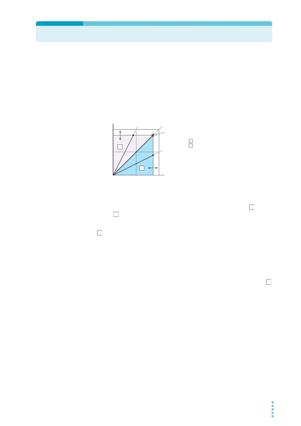
The above figure shows the PWR-01 operation modes. The load resistance is denoted as RL.
The resistance, which is denoted as Rc, is calculated from the set voltage and current (Rc =
Vs/ Is). The power supply is designed so that it operates in CV mode in area and CC
mode in area . The boundary is the line defined by R
L = Rc. This line represents the load at
which the output voltage and the set voltage are equal and the output current and the set cur-
rent are equal. If load resistance RL is greater than resistance RC, the operating point is in
area , and the PWR-01 operates in CV mode (point p). In this case, the set current Is
equals the current limit.
When the PWR-01 is operating in CV mode, the output voltage is maintained at the set volt-
age. Output current I is determined by the equation I = Vs/RL and is a current that is less than
current limit Is. The actual current that flows is not necessarily equal to the specified value.
For loads in which transient peak current flows, current limit Is must be set higher than the
peak value.
Conversely, if load resistance R
L is less than resistance Rc, the operating point is in area ,
and the PWR-01 operates in CC mode (point q). In this case, set voltage Vs equals the volt-
age limit.
When the PWR-01 is operating in CC mode, the output current is maintained at the set cur-
rent. Output voltage V is determined by the equation V = Is x R
L and is a voltage that is less
than voltage limit Vs. The actual voltage that is applied is not necessarily equal to the speci-
fied value.
For loads that generate transient surge voltage, voltage limit Vs must be set higher than the
surge voltage.
Crossover point
The PWR-01 switches automatically between CV mode and CC mode according to the
changes in the load. A crossover point is the point at which the mode switches.
For example, when operating in CV mode, if the load changes and the output current reaches
the current limit, the PWR-01 automatically switches to CC mode to protect the load. Like-
wise, when operating in CC mode, if the output voltage reaches the voltage limit, the PWR-01
switches to CV mode.
Crossover point
A = CV mode area
B = CC mode area
Vs = Set voltage
Is = Set current
Rc = Vs/ Is (Ohm’s Law)
RL = Load resistance
Vmax = Maximum settable voltage
Imax = Maximum settable current