24 PWR-01
Connecting to the Output Terminals
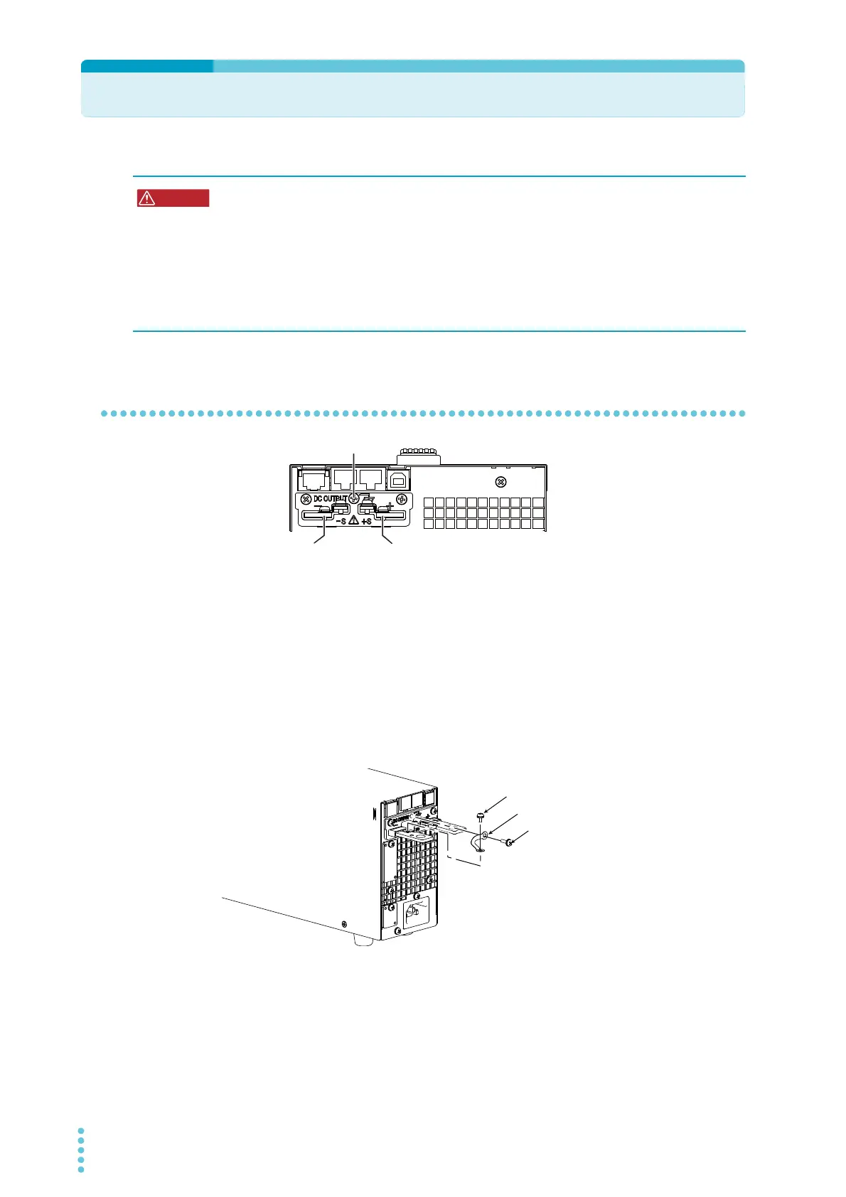
Connecting to the rear-panel output terminals
1
Turn the POWER switch off.
Check that there is no residual voltage at the rear-panel output terminals.
2
Connect one end of the included chassis connection short bar to the
chassis terminal and the other end to the negative or positive output ter-
minal.
Use the screw on the PWR-01 to connect the short bar to the chassis terminal. Use the
screw on the rear-panel output terminal to connect the short bar to the output terminal.
If you are not grounding the output terminal (leaving it floating), refer to “Output Termi-
nal Insulation” (p.22) before use.
3
Attach crimping terminals to the load cables.
The rear-panel output terminals have holes for connecting the load cables. Use crimp-
ing terminals that are appropriate for the bolts that you are using.
Risk of electric shock.
• Turn the POWER switch off before you touch the rear-panel output terminals.
• Even if you turn the output off or turn the POWER switch off, if the bleeder circuit is
set to off (CF01: DIS), the voltage that was present when the output was on will
remain at the output terminals. Set the bleeder circuit to on (CF01: NORM/ HYP)
before you touch the output terminals.
• Regardless of whether load cables are connected to the output terminals, be sure to
attach the OUTPUT terminal cover before turning the POWER switch on.
Chassis terminal
íQHJDWLYHWHUPLQDO
SRVLWLYHWHUPLQDO
Chassis connection short bar
Screw (M3)
Screw (M3)
400W model
Example of connecting to the negative terminal