PWR-01 25
Installation and Preparation | Connecting to the Output Terminals
4
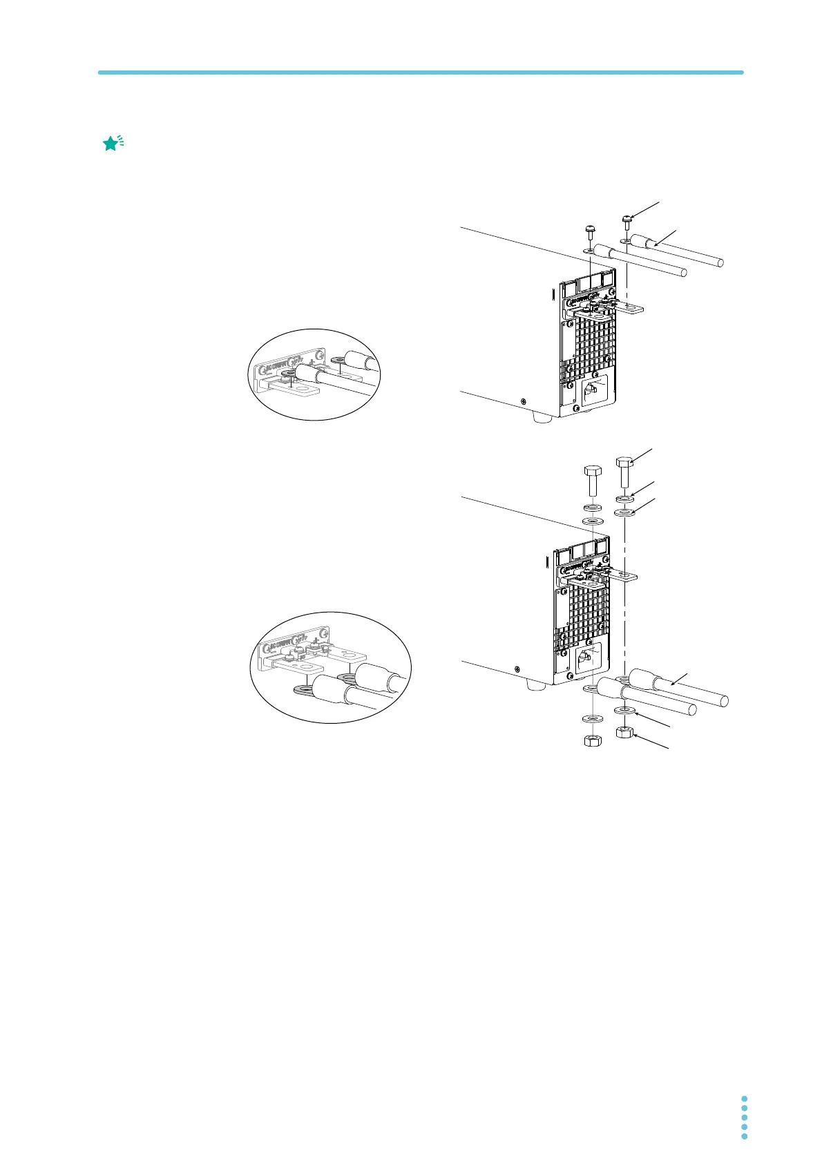
Connect the load cables to the rear-panel output terminals.
Use the included screw set.
To reduce the influence of noise on the output, keep the cables as short as possible. If
possible, twist the positive and negative load cables.
Attaching the OUTPUT terminal cover
You can adjust the diameter of the holes that the load cables pass through by changing the
orientation of the adapter attached to the OUTPUT terminal cover. There are two available
orientations. Use the appropriate orientation for the load cables (including the insulation) that
you are using.
• Cable diameter (including the insulation) up to ø7: Attach the adapter of the OUTPUT
terminal cover so that the hole diameter is small.
• Cable diameter (including the insulation) from ø8 to ø17: Attach the adapter of the
OUTPUT terminal cover so that the hole diameter is large.
If you do not connect load
cables in the correct
orientation, you will not be
able to attach the
OUTPUT terminal cover.
Spring washer
(M8)
Washer (M8)
Washer (M8)
Nut (M8)
Using the M8 bolt set to connect the cables
Cable diameter (including the insulation)
ø8 to ø17
Applicable models
L type, ML type
Connection using the M4 screw set
Cable diameter (including the insulation)
Up to ø7
Applicable models
All models
400W model example
Bring the ring to the bottom
side, and align to the bottom
Bring the ring to the bottom
side, and align to the top side