30 PWR-01
Remote Sensing function
Remote sensing is a function that stabilizes the output voltage across the load by reducing
the influence of voltage drops and other effects caused by the load cable resistance.
The PWR-01 remote sensing can compensate up to the values shown below. Select a load
cable that has sufficient current capacity to prevent the voltage drop in the load cable from
exceeding the compensation voltage.
When you perform remote sensing, set the voltage of the sensing point (across the load) so
that it does not exceed the rated output voltage. If you are performing remote sensing with
the voltage close to the maximum output voltage, the output is limited by the maximum output
voltage (105 % of the rated output voltage). Electrolytic capacitors may be required at the
sensing point (across the load).
To reduce the effect of noise, use twisted-pair cables or 2-core shielded cables. When you
use shielded cables, connect the shield to the PWR-01 or the load grounding terminal.
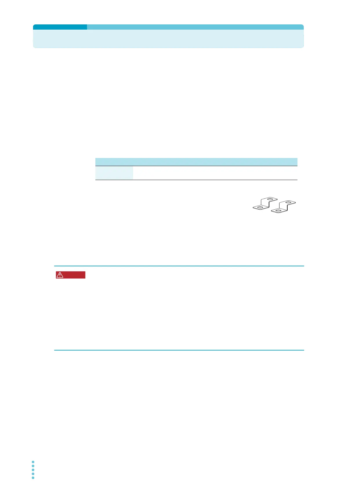
When the product is shipped from the factory, a sensing short bar
is connected across the sensing terminals and DC OUTPUT termi-
nals. When the sensing terminals are not used, connect the sens-
ing short bar.
If the short bar is damaged or lost, contact your Kikusui agent or
distributor.
Connecting the sensing cables
L type ML type MH type H type
Compensation
voltage
Approx. 1.5 V one
way
Approx. 4 V one
way
Approx. 5 V one
way
Approx. 5 V one
way
Risk of electric shock and damage to internal circuits.
• Never wire the sensing terminals while the POWER switch is turned on.
• For sensing cables, use cables with a voltage rating that is higher than the PWR-01’s
isolation voltage. Protect the uncovered sections of the shielded cable by using
insulation tubes whose withstand voltage is greater than the PWR-01’ isolation volt-
age.
• Even if you turn the output off or turn the POWER switch off, if the bleeder circuit is
set to off (CF01: DIS), the voltage that was present when the output was on will
remain at the output terminals. Set the bleeder circuit to on (CF01: NORM/ HYP)
before you touch the sensing terminals.
• Be sure to attach the OUTPUT terminal cover before turning the POWER switch on.