PWR-01 31
Installation and Preparation | Remote Sensing function
If the sensing cables come loose, the output voltage will rise several volts. To prevent voltage
output exceeding the voltage setting, set an appropriate OVP trip point.
After you finish using remote sensing, connect the sensing short bar.
1
Turn the POWER switch off.
2
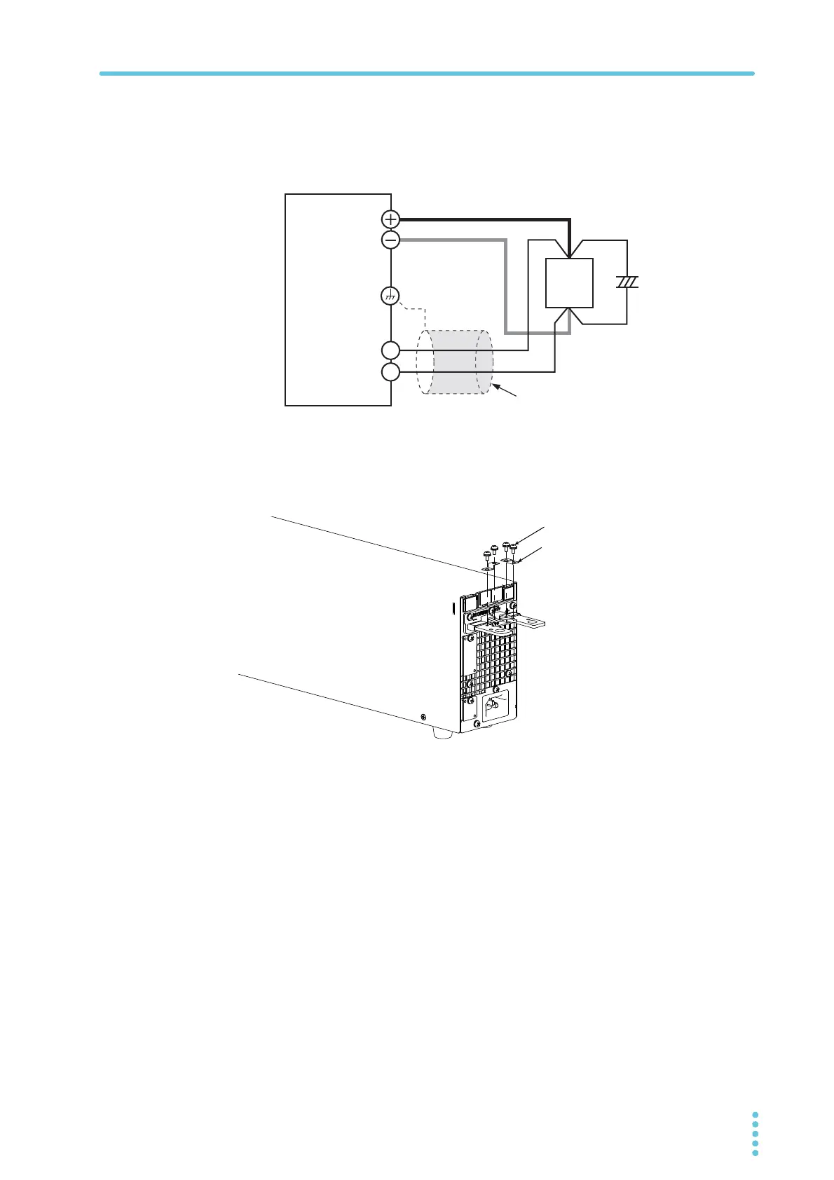
Remove the sensing short bar that is connected across the sensing ter-
minals and DC OUTPUT terminals.
3
Attach crimping terminals to the sensing cables, and connect the sens-
ing terminals to the sensing point (across the load).
Attach crimping terminals that match the screws to be used, and securely fasten the
cables.
If you cannot use shielded cables, twist the positive and negative cables sufficiently.
+
+
–
–
Capacitor
+S
-S
Connect an
electrolytic
capacitor
across the
Output terminal
Chassis terminal
Sensing terminal
Sensing short bar
Screw (M3x6)