76 PWR-01
Bleeder Circuit function
Turn the bleeder circuit off when you do not want the internal bleeder circuit to sink output
current. When you connect a battery, you can prevent excessive electrical discharges by
turning the bleeder circuit off.
Set the bleeder circuit to off, normal bleeder, or hyper bleeder using a CONFIG setting
(CF01).
When the POWER switch is turned on the next time, the PWR-01 starts with the settings that
were in use the last time that the POWER switch was turned off.
When using master-slave parallel operation or series operation, use the same settings on all
connected units. You can also specify this parameter when the PWR-01 is being used as a
slave unit.
Depending on whether the bleeder circuit setting, the sink current when an external voltage
source is connected will vary.
Sink current (reference value) from an external voltage source according
to the bleeder circuit setting
Risk of electric shock. Set the bleeder circuit to on (CF01: NORM/ HYP) before you
touch the output terminals. If it is set to off (CF01: DIS), the voltage that was present
when the output was on will remain at the output terminals even if you turn off the out-
put or POWER switch.
Bleeder circuit Displayed
setting
Description
Off
1
1 Even if the output terminals are open and the output is turned off or the voltage setting is at 0 V, up
to several hundred millivolts of voltage may appear across the output terminals.
DIS Bleeder circuit off
Normal bleeder NORM Bleeder circuit on
Hyper bleeder HYP Bleeder circuit on.
HB lights on the display. The fan speed is fixed to the maximum
speed.
Provides strong sink performance (see the table below).
The fall time at no load is reduced to about 70 % of that using the
normal bleeder (reduction in test cycle time (takt time) is possible).
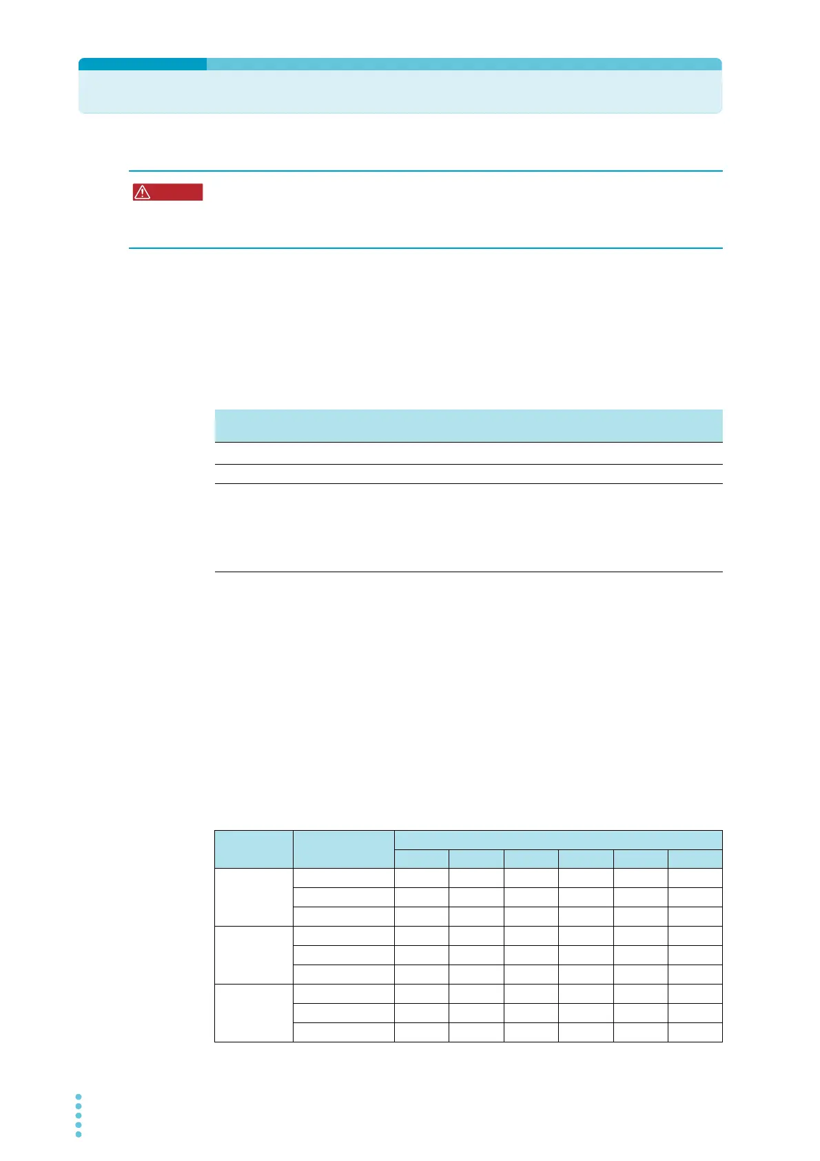
Vout= Output terminal voltage
Model Bleeder circuit
Sink current
5Vout 10 Vout 15 Vout 20 Vout 30 Vout 40 Vout
PWR401L Off 0.000 A 0.000 A 0.001 A 0.001 A 0.002 A 0.003 A
Normal bleeder 0.381 A 0.347 A 0.312 A 0.277 A 0.208 A 0.139 A
Hyper bleeder 0.583 A 0.546 A 0.512 A 0.477 A 0.409 A 0.339 A
PWR801L Off 0.000 A 0.000 A 0.000 A 0.001 A 0.001 A 0.001 A
Normal bleeder 0.730 A 0.660 A 0.590 A 0.525 A 0.386 A 0.248 A
Hyper bleeder 1.130 A 1.060 A 1.000 A 0.930 A 0.780 A 0.640 A
PWR1201L Off 0.000 A 0.001 A 0.001 A 0.001 A 0.001 A 0.002 A
Normal bleeder 1.120 A 1.010 A 0.900 A 0.792 A 0.577 A 0.362 A
Hyper bleeder 1.720 A 1.620 A 1.510 A 1.410 A 1.200 A 1.000 A