PWR-01 47
Basic Features | Protection functions and Alarms
Alarm signal
Alarm signal is generated from pin 14 of the J1 connector if PRL ALM or SD is activated. The
J1 connector is at approximately the same electric potential as the negative output terminal.
Alarm signal is generated from pin 4 of the J2 connector if OVP, OCP, FOCP, OHP, SENSE,
AC-FAIL, WATCHDOG, or SD is activated. The signal is isolated from other terminals through
an open collector photocoupler.
Setting the protection functions
Overvoltage protection (OVP)
The overvoltage protection function is activated when the output terminal voltage exceeds the
set voltage (OVP trip point).
You need to set an appropriate OVP trip point. Immediately after you purchase the PWR-01
or immediately after a load is changed, set the OVP trip point to a value that is appropriate for
the load.
If the voltage setting limit is set to on (CF23: ON), you cannot set an OVP trip point that is
lower than the voltage setting.
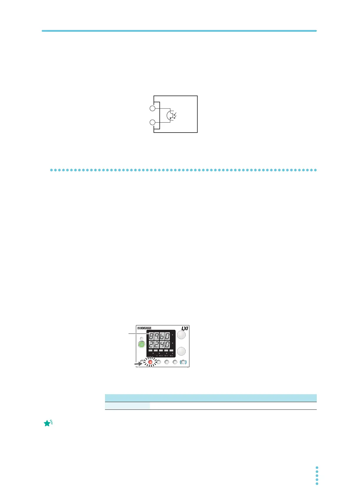
Setting the OVP trip point
OVP operates on the output terminal voltage. If you want to activate the protection function
according to the voltage across the load, take the voltage drop in the load cable into consider-
ation when you set the OVP trip point.
1
Press OVP•OCP.
The OVP•OCP key lights, and the voltmeter displays the present OVP trip point.
2
Turn the VOLTAGE knob to set the OVP trip point.
OVP setting range: 10 % to 112 % of the rated output voltage
3
Press OVP•OCP twice to finish the configuration.
The OVP trip point will be set. The OVP•OCP key turns off, and the measured value
display appears.
Maximum voltage: 30 V
Maximum current: 8 mA
STATUS COM
L type ML type MH type H type
OVP setting range 4 V to 44.8 V 8 V to 89.6 V 24 V to 268.8 V 65 V to 728 V
OVP trip point indication
CV
CC
/
W
V
A
AL M RMT LOCK LAN
BCA
PRESET
DLY SEQ HBSSVIR
CV
CC
/
W
V
A
AL M RMT LOCK LAN
SC2 SC3 LOCKALM CLR SC1
SHIFT
FINE
FINE
REGULA TED DC POWER SUPPLY
OUTPUT
VOLTAGE
CURRENT
CONFIG
PWR DSPLMEMORY
LOCALSET OVP•OCP
Lit
OVP
Trip point
Press PWR DSP L to
cancel the confirmation of
the parameter.