48 PWR-01
Basic Features | Protection functions and Alarms
Checking OVP operation
If the voltage setting limit is set to on (CF23: ON), the output voltage cannot be set higher than
the OVP trip point, so you cannot verify the OVP operation.
1
Check that the OUTPUT LED is turned off.
2
Set the output voltage to a value lower than the OVP trip point.
3
Press OUTPUT to turn output on.
The OUTPUT LED lights.
4
Slowly turn the VOLTAGE knob clockwise until the OVP is activated.
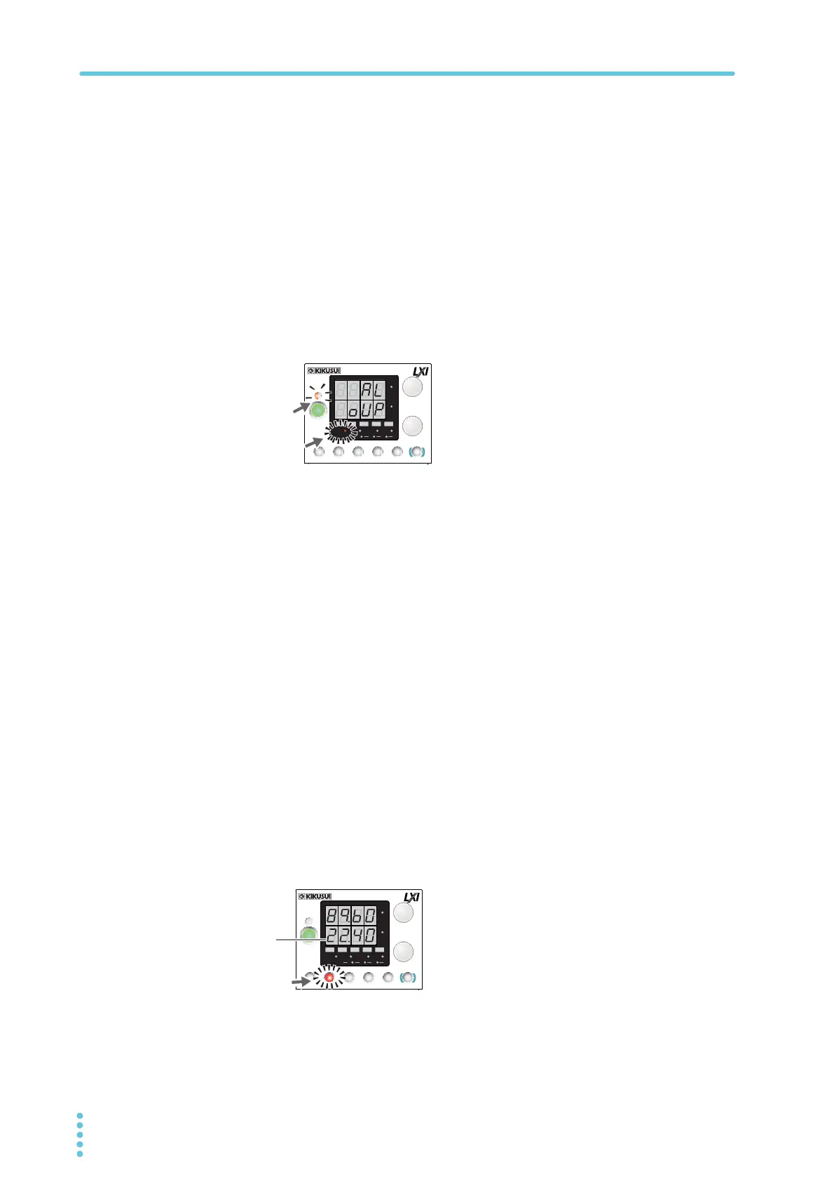
When the output voltage exceeds the OVP trip point, an alarm will occur. The ALM
LED lights, and the OUTPUT LED blinks.
5
Check that output has turned off.
6
Press ALM CLR (SHIFT + SET) to clear the alarm.
If you do not change the output voltage, the OVP will be activated again.
Overcurrent protection (OCP)
The overcurrent protection (OCP) function is activated when the output current exceeds the
set current (OCP trip point).
You need to set an appropriate OCP trip point. Immediately after you purchase the PWR-01
or immediately after a load is changed, set the OCP trip point to a value that is appropriate for
the load.
If the current setting limit is set to on (CF22: ON), you cannot set an OCP trip point that is
lower than the current setting.
You can set the detection time of OCP activation.
Setting the OCP trip point
1
Press OVP•OCP.
The OVP•OCP key lights, and the ammeter displays the present OCP trip point.
Alarm indication when OVP is activated
CV
CC
/
W
V
A
AL M RMT LOCK LAN
BCA
PRESET
DLY SEQ HBSSVIR
CV
CC
/
W
V
A
AL M RMT LOCK LAN
SC2 SC3 LOCKALM CLR SC1
SHIFT
FINE
FINE
REGULA TED DC POWER SUPPLY
OUTPUT
VOLTAGE
CURRENT
CONFIG
PWR DSPLMEMORY
LOCALSET OVP•OCP
Lit
Blinking
(orange)
OCP trip point indication
CV
CC
/
W
V
A
AL M RMT LOCK LAN
BCA
PRESET
DLY SEQ HBSSVIR
CV
CC
/
W
V
A
AL M RMT LOCK LAN
SC2 SC3 LOCKALM CLR SC1
SHIFT
FINE
FINE
REGULA TED DC POWER SUPPLY
OUTPUT
VOLTAGE
CURRENT
CONFIG
PWR DSPLMEMORY
LOCALSET OVP•OCP
Lit