22 PWR-01
Output Terminal Insulation
The cable and load that are connected to the output terminal (including the sensing terminal)
must have an insulation capacity that is greater than or equal to the isolation voltage of the
PWR-01 with respect to the chassis. Isolation voltage indicates the maximum allowed voltage
that appears across the output terminal of the power supply unit and the protective conductor
terminal (chassis terminal).
When the output terminal is not grounded (floating)
The output terminal of the PWR-01 is isolated from the protective conductor terminal. If you
connect the GND wire of the power cord to the ground terminal of the switchboard, the chas-
sis of the PWR-01 is set to ground potential.
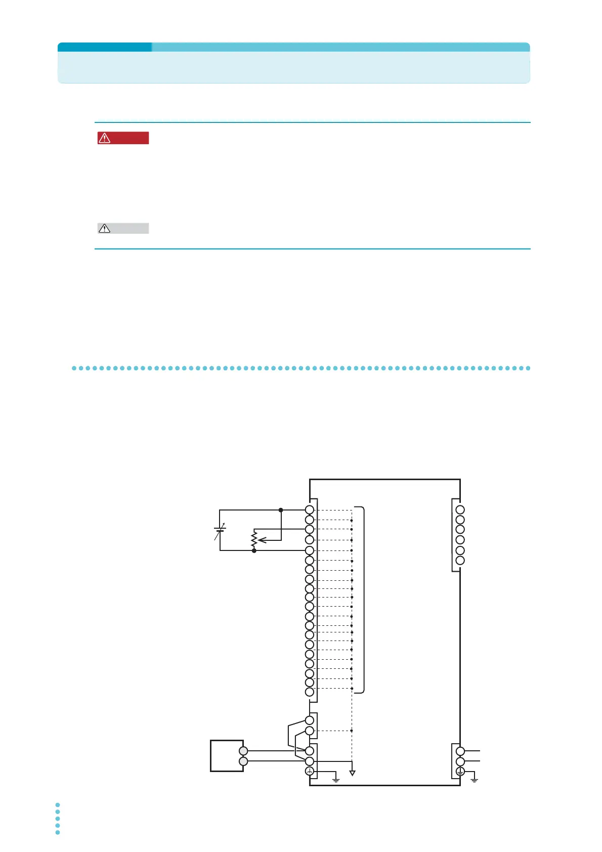
The J1 connector on the rear panel are at approximately the same electric potential as the
PWR-01’s negative output terminal. Cables and devices that are connected to these pins
must have an insulation capacity greater than or equal to the isolation voltage of the PWR-01.
Risk of electric shock. For safety reasons, even if the output terminal is grounded,
make sure that the insulation capacity of the output terminal (including the sensing
terminal) is greater than or equal to the isolation voltage of this product.
For details on the isolation voltage of each model, see "Specifications" (p.117).
If you cannot obtain a cable with sufficient rated voltage, secure adequate withstand
voltage by passing the cable through an insulation tube with a withstand voltage
greater than the isolation voltage of the PWR-01.
The signal cable may burn out. If the PWR-01 is to be controlled through an external voltage
(Vext), do not ground the external voltage (leave it floating).
+
–
+
+S
–S
–
+
–
16
17
18
19
14
15
20
2
3
4
5
6
13
12
11
10
9
8
7
1
2
3
4
5
6
1
AC
INPUT
DC
OUTPUT
J1 J2
SENS
L
N
Load
Rext
PWR-01
Vext
Approximately the same
electric potential as the
negative output terminal
All pins of the J1 connector are at
approximately the same electric
potential as the PWR-01’s nega-
tive output terminal.