94 PWR-01
Controlling the Output On and Off States
This section explains how to use an external contact to control the output on and off states.
To reduce the influence of noise on the output, connect a 2-core shielded wire or a twisted-
pair wire across the external contact, and keep the wire as short as possible. If the wiring is
long, it becomes easy for noise to influence the operation of the PWR-01. Even if you use
cables that are designed to suppress noise, the PWR-01 may not operate properly.
If you use a shielded cable, connect the shield to the negative output terminal.
To use an external contact to control the output on and off states, set the appropriate CON-
FIG parameter (CF15:
ON). Then, select the logic setting from the following two options.
• Turn the output on with a low signal (CF15:
LO)
Output is turned on when a low (0 V to 0.5 V) signal is applied to pin 17 of the J1 connec-
tor or the pin is shorted.
• Turn the output on with a high signal (CF15: HI)
Output is turned on when a high (4.5 V to 5 V) signal is applied to pin 17 of the J1 connec-
tor or the pin is opened.
When you are using an external contact to turn the output off, the OUTPUT key on the front
panel becomes invalid.
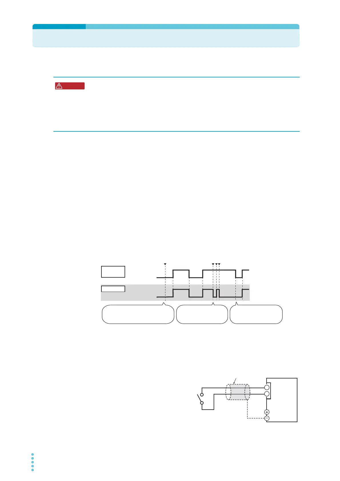
Controlling the output on and off states (in this example, a high signal is used to turn the
output on)
External contact connection
Use pins 15 and 17 of the J1 connector.
The open-circuit voltage across pins 15 and
17 is approximately 5 V. The short-circuit
current across pins 5 and 19 is approxi-
mately 0.5 mA.
Use external contacts that have a contact
rating greater than or equal to 0.5 mA at
5Vdc.
Risk of electric shock.
• Ensure that the insulation of external contact (S) and the connected cable is greater
than or equal to the isolation voltage of the PWR-01. For details on the isolation volt-
age of each model, see Chap.7 "Specifications" (p.117).
• When using shielded cables for the connection, protect the uncovered sections of
the shielded cable by using insulation tubes whose withstand voltage is greater than
the PWR-01’s isolation voltage.
źUHSUHVHQWVWKDWWKH287387NH\KDVEHHQSUHVVHG
([WHUQDO
FRQWDFW
2XWSXW
7KH287387VZLWFKLV
YDOLGEHFDXVHWKHRXWSXW
LVWXUQHGRQWKURXJKWKH
H[WHUQDOFRQWDFW
7RRXWSXWDJDLQWKURXJK
WKHH[WHUQDOFRQWDFWILUVW
WXUQWKHRXWSXWRII
287387NH\GLVDEOHG1RRXWSXWLV
SURGXFHGHYHQLI\RXSUHVVWKH
VZLWFKEHFDXVHWKHRXWSXWLVWXUQHG
RIIWKURXJKWKHH[WHUQDOFRQWDFW
2-core shielded wire or
twisted pair wires
Output terminal
J1
17
15
PWR-01
Switch