20 PWR-01
Selecting the Load Cables
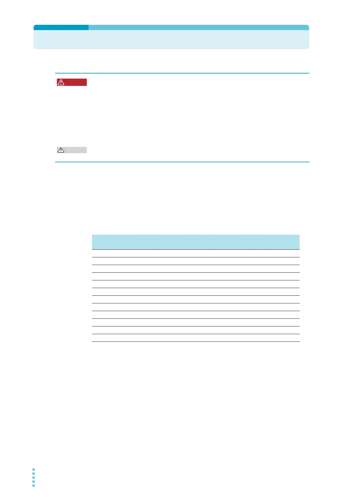
Current capacity of load cables
A cable’s temperature is determined by the resistive loss based on the current, the ambient
temperature, and the cable’s external thermal resistance. The following table shows the cur-
rent capacity of heat-resistant vinyl cables that have a maximum allowable temperature of
60 °C when one of the cables is separated and stretched out horizontally in air in an ambient
temperature of 30 °C. The current must be reduced under certain conditions, such as when
vinyl cables that have a low heat resistance are used, when the ambient temperature is 30 °C
or greater, or when cables are bundled together and little heat is radiated.
Taking measures against noise
When connecting cables that have the same heat resistance, separating the cables as much
as possible to increase heat radiation enables a greater amount of current to flow. However,
wiring the + (positive) and - (negative) output wires of the load cable side by side or bundling
them together is more effective against unwanted noise. The Kikusui-recommended currents
shown in the above table are allowable currents that have been reduced in consideration of
the potential bundling of load cables. Use these values as a guideline when connecting
cables.
Risk of fire.
• Use load cables whose capacity is adequate for the PWR-01’s rated output current.
• The output terminal and its surrounding area become very hot. Use cables whose
covers have an allowable temperature of 85 °C or higher.
Risk of electric shock.
• Use load cables with a voltage rating that meets or exceeds the product’s isolation
voltage. For details on the PWR-01’s isolation voltage, see Chap.7 "Specifica-
tions"(p.117).
• Use load cables with a core diameter that is appropriate for the amount of current being
used and with sturdy, flame-resistant insulation.
Nominal cross-
sectional area (mm
2
)
AWG (reference cross-
sectional area; mm
2
)
Allowable current
1
(A)
(Ta = 30 °C)
1 Excerpt from Japanese laws related to electrical equipment.
Kikusui-recom-
mended current (A)
2 14 (2.08) 27 10
3.5 12 (3.31) 37 -
5.5 10 (5.26) 49 20
8 8 (8.37) 61 30
14 6 (13.3) 88 50
22 4 (21.15) 115 80
30 2 (33.62) 139 -
38 1 (42.41) 162 100
50 1/0 (53.49) 190 -
60 2/0 (67.43) 217 -
80 3/0 (85.01) 257 200
100 4/0 (107.2) 298 -