16 PWR-01
Installation and Preparation | Connecting the Power Cord
Necessary cable
Vinyl cabtire cable (VCTF): Nominal cross-sectional area 5.5 mm
2
3core
Finished diameter: 12.1 mm or less
Rated voltage: 250 V or higher
Input terminal end: Ring terminal 5.5-4 (5.5 mm
2
M4)
Connection procedure
1
Check that the AC power line meets the nominal input rating of the prod-
uct.
The product can receive a nominal line voltage in the range of 100 Vac to 240 Vac at
50 Hz or 60 Hz.
2
Check that the POWER switch is turned off.
3
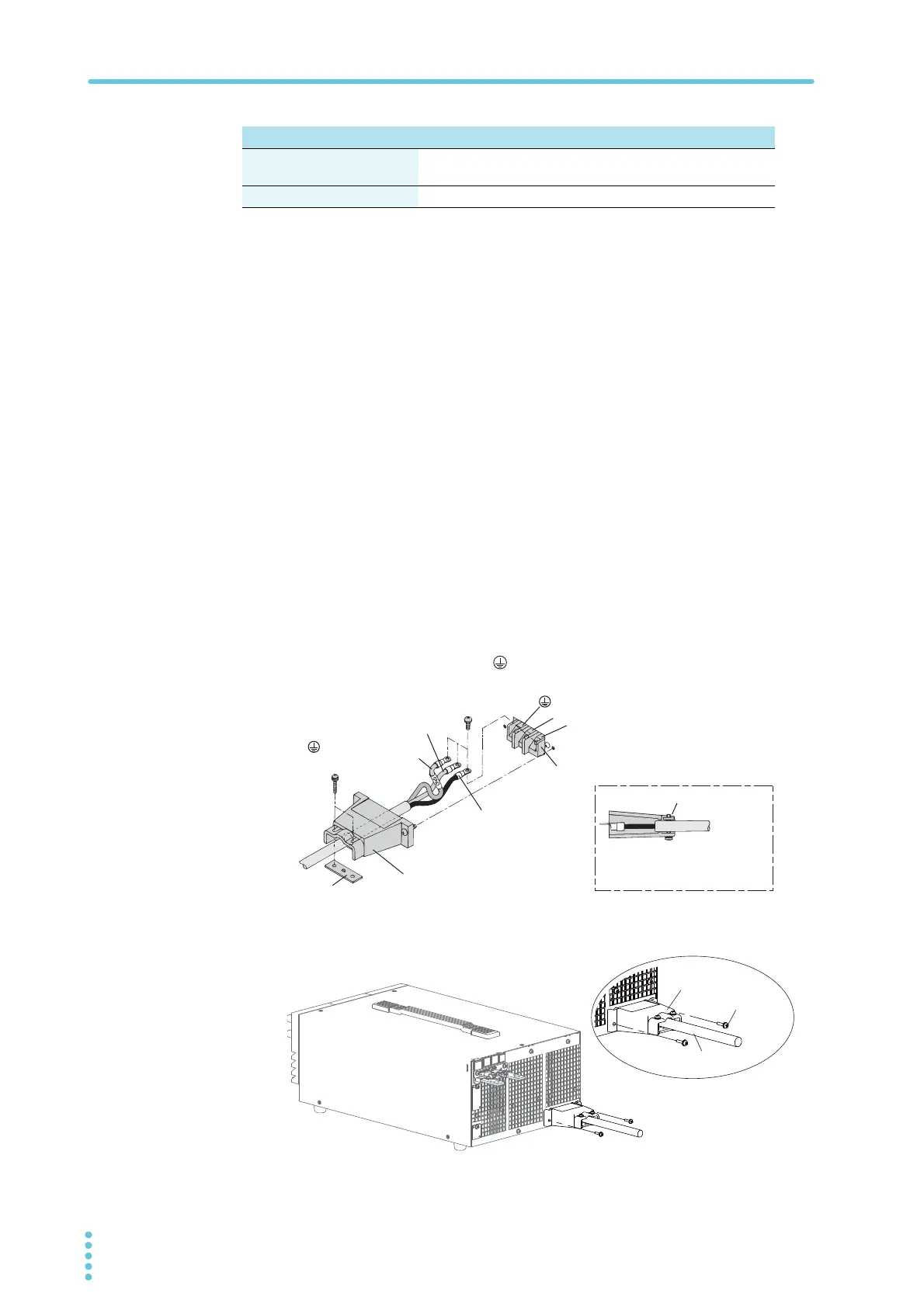
Connect the power cord to the AC INPUT terminal on the rear panel.
Pass the power cord through the included INPUT terminal cover, and fix
the cord in place using the lock plate and screws.
Be sure to connect the L, N, and (GND) of the AC input terminal correctly.
4
Attach the INPUT terminal cover using the screws on the PWR-01.
5
Attach the included ferrite core to the power cord.
400W model 800W model 1200W model
Protective conductor current
(at 265 Vac, 60 Hz)
1.5 mA 2.5 mA 4.0 mA
Inrush current 25 Amax 50 Amax 75 Amax
Input terminal cover
N
L
(GND)
AC INPUT terminal block
N: White or blue
L: Black or brown
Lock plate
Lock plate
(GND): Green or
green and yellow
Secure the insulated section
of the power cord in place
with a lock plate.
Power cord
Screw
Input terminal cover