PWR-01 49
Basic Features | Protection functions and Alarms
2
Turn the CURRENT knob to set the OCP trip point.
OCP setting range: 10 % to 112 % of the rated output current
3
Press OVP•OCP twice to finish the configuration.
The OCP trip point will be set. The OVP•OCP key turns off, and the measured value
display appears.
Setting the detection time of OCP activation
You can set the amount of time that elapses after the OCP trip point is exceeded (the amount
of time during which the OCP trip point is continuously exceeded) before the output is turned
off (CF24). This is useful when you do not want the output to be turned off due to short-term
overloads.
Checking OCP operation
If the current setting limit is set to on (CF22: ON), the output current cannot be set higher than
the OCP trip point, so you cannot verify the OCP operation.
1
Short the output terminals.
2
Turn the POWER switch on.
3
Check that the OUTPUT LED is turned off.
4
Set the output current to a value lower than the OCP trip point.
5
Press OUTPUT to turn output on.
The OUTPUT LED lights.
6
Slowly turn the CURRENT knob clockwise until the OCP is activated.
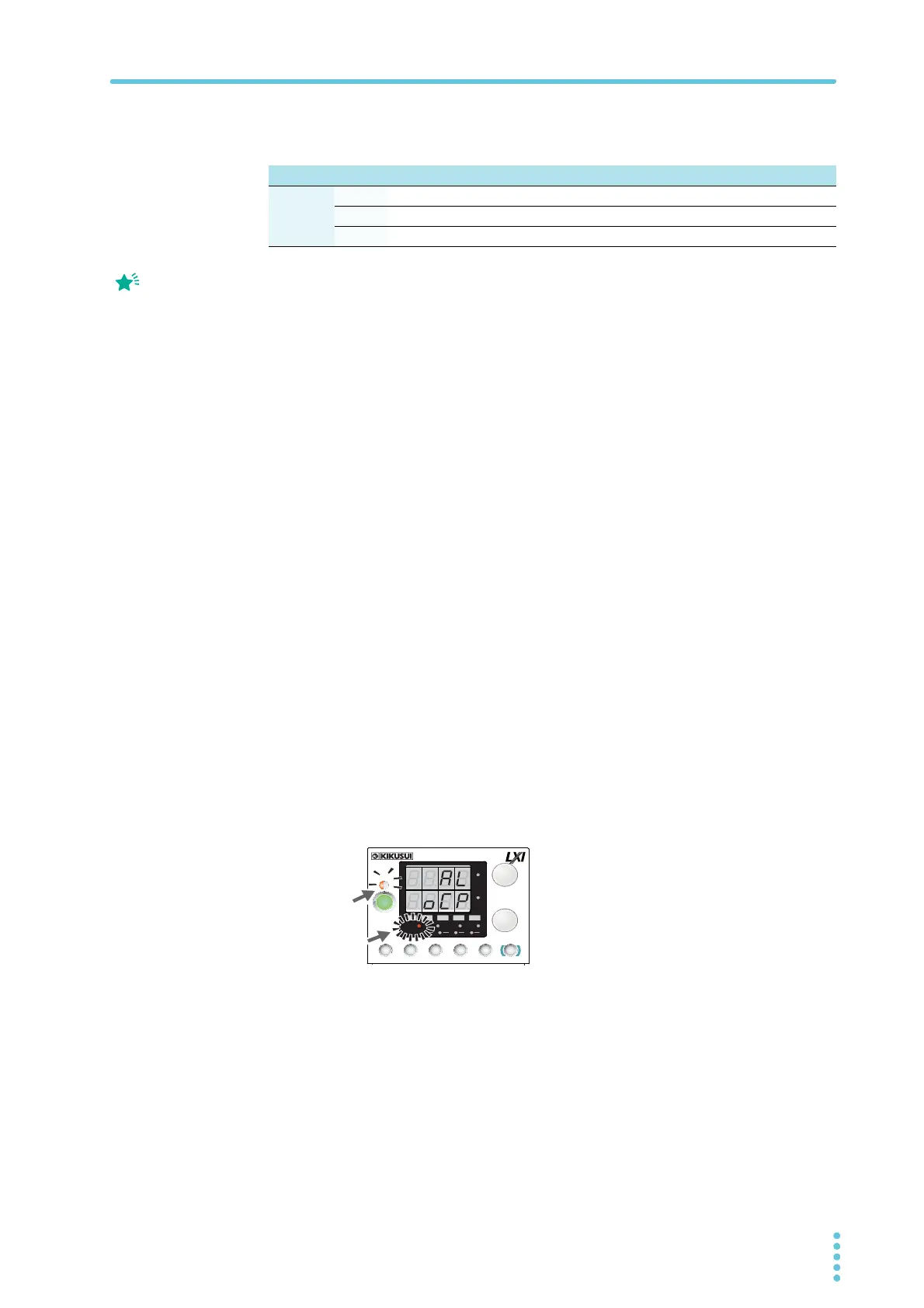
When the output current exceeds the OCP trip point, an alarm will occur. The ALM
LED lights, and the OUTPUT LED blinks.
7
Check that output has turned off.
8
Press ALM CLR (SHIFT + SET) to clear the alarm.
If you do not change the output current, the OCP will be activated again.
L type ML type MH type H type
OCP
Setting
range
400 W
4 A to 44.8 A 2 A to 22.4 A 0.5 A to 5.6 A 0.185 A to 2.072 A
800 W
8 A to 89.6 A 4 A to 44.8 A 1 A to 11.2 A 0.37 A to 4.144 A
1200 W
12 A to 134.4 A 6 A to 67.2 A 1.5 A to 16.8 A 0.555 A to 6.216 A
Press PWR DSP L to
cancel the confirmation of
the parameter.
Alarm indication when OCP is activated
CV
CC
/
W
V
A
AL M RMT LOCK LAN
BCA
PRESET
DLY SEQ HBSSVIR
CV
CC
/
W
V
A
AL M RMT LOCK LAN
SC2 SC3 LOCKALM CLR SC1
SHIFT
FINE
FINE
REGULA TED DC POWER SUPPLY
OUTPUT
VOLTAGE
CURRENT
CONFIG
PWR DSPLMEMORY
LOCALSET OVP•OCP
Lit
Blinking
(orange)