PWR-01 91
External Control | Output voltage control
If you use a shielded cable, connect the shield to the negative output terminal. If the shield
needs to be connected to the Vext side, see "Notes for Connecting External Voltage
(Vext)"(p.88).
Use pins 1 and 5 of the J1 connector.
Control using an external resistance (Rext)
By using an external resistance (Rext) to change the voltage-divider ratio of the reference
voltage (J1-3 REF OUT), you can change the output voltage (Eo) to a value in the range of 0
to the 105 % of the rated output voltage (Ertg).
To use an external resistance (Rext) to control the output voltage, set CV control using an
external voltage or external resistance to on (CF11:
ON) in CONFIG settings.
In CONFIG settings (CF12), set the external voltage (Vext) range and reference voltage (J1-3
REF OUT).
The output voltage (Eo) varies in the range of 0 to the rated output voltage (Ertg) when the
external voltage (Vext) is changed in the range of 0 V to 5 V (CF12:
LO) or in the range of 0 V
to 10 V (CF12: HI).
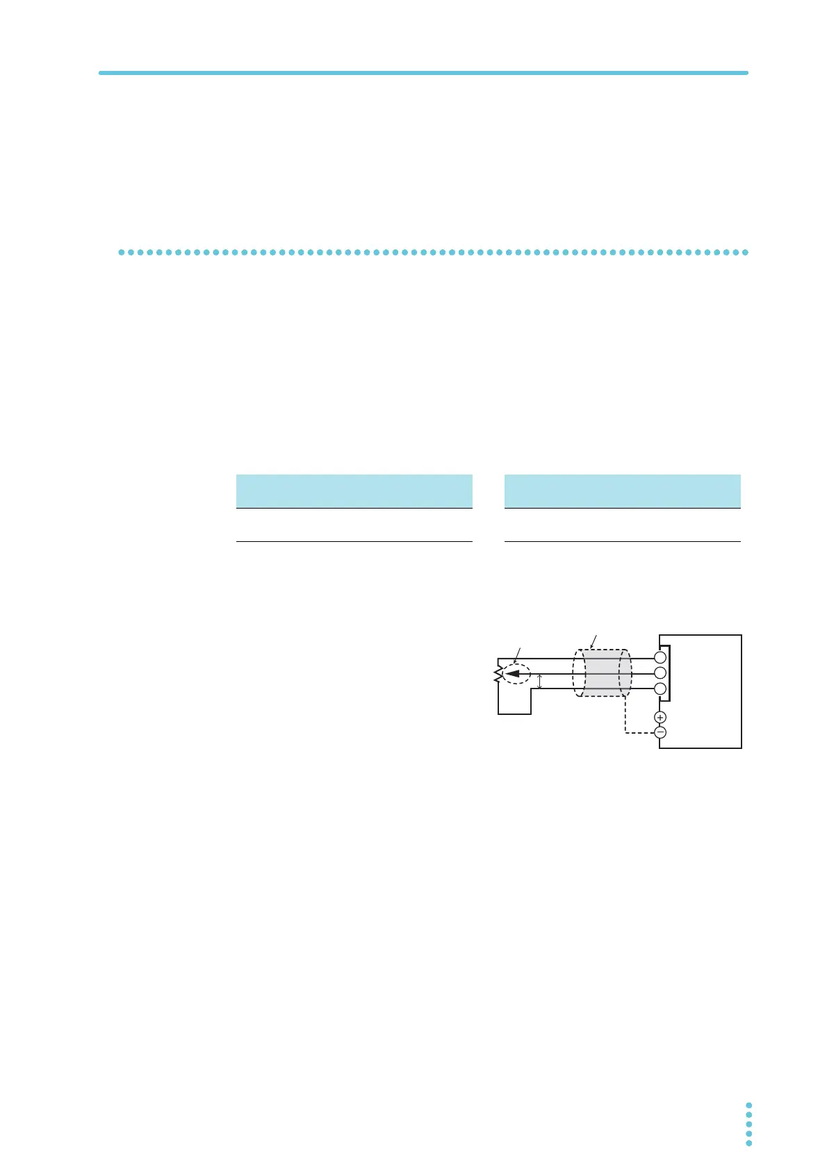
External resistance (Rext) connection
For Rext, use a resistor that is rated at
approximately 10 kΩ, 1/2 W or greater,
that has a low temperature coefficient,
and that will change little over time.
Examples of such resistors are metal
film or wire wound resistors.
To reduce the influence of noise on the
output, connect a 2-core shielded wire
or a twisted-pair wire across Rext, and
keep the wire as short as possible. If
the wiring between the PWR-01 and
the external contact is long, it becomes easy for noise to influence the operation of the PWR-
01. Even if you use cables that are designed to suppress noise, the PWR-01 may not operate
properly.
If you use a shielded cable, connect the shield to the negative output terminal.
Use pins 3, 1, and 5 of the J1 connector.
Reference voltage (REF OUT) 5.25 V
External voltage (Vext) 0 V to 5 V (CF12: LO)
Reference voltage (REF OUT) 10.5 V
External voltage (Vext) 0 V to 10 V (CF12: HI)
Eo = Ertg×Vext /5 [V]
Vext = 5×Eo /Ertg [V]
Eo = Ertg×Vext /10 [V]
Vext = 10×Eo /Ertg [V]
twisted pair wires
Wiper
Output terminal
J1
3
1
5
PWR-01
Reference
voltage
(REF OUT)
Vext