32 PWR-01
Installation and Preparation | Remote Sensing function
Electrolytic capacitor to connect across the load
If the wiring inductance component is large, the following symptoms may appear.
• Oscillation
If the wires used to connect to the load are long, the wiring inductance and capacitance
can cause phase shifting at a level that cannot be ignored. This may lead to oscillation.
• Output fluctuation
If the load current changes drastically in a pulse-shaped pattern, the output voltage may
become large due to the wiring’s inductance component.
You can reduce the inductance component by twisting the load cables, which stabilizes the
voltage. However, if this does not correct the problem, connect an electrolytic capacitor
across the load.
Electrolytic capacitor to use
Capacitance: 0.1 µF to several 100 µF
Withstanding voltage: At least 120 % of the rated output voltage of the PWR-01
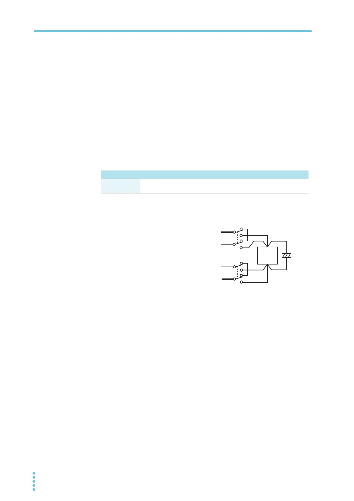
If you are inserting a mechanical switch between the PWR-01 and the load
If you want to connect and disconnect the
load using a mechanical switch that is
inserted between the PWR-01 and the load,
be sure to include switches in the sensing
cables as shown in the following figure and
turn on and off the load cable and the sens-
ing cables simultaneously. Before you turn
the mechanical switch on or off, be sure to
turn off the OUTPUT key.
L type ML type MH type H type
Withstanding
voltage
48 V or more 96 V or more 288 V or more 780 V or more
Load
Switch
+
–
Capacitor
+
–
+S
–S
+
–