PWR-01 89
External Control | Notes for Connecting External Voltage (Vext)
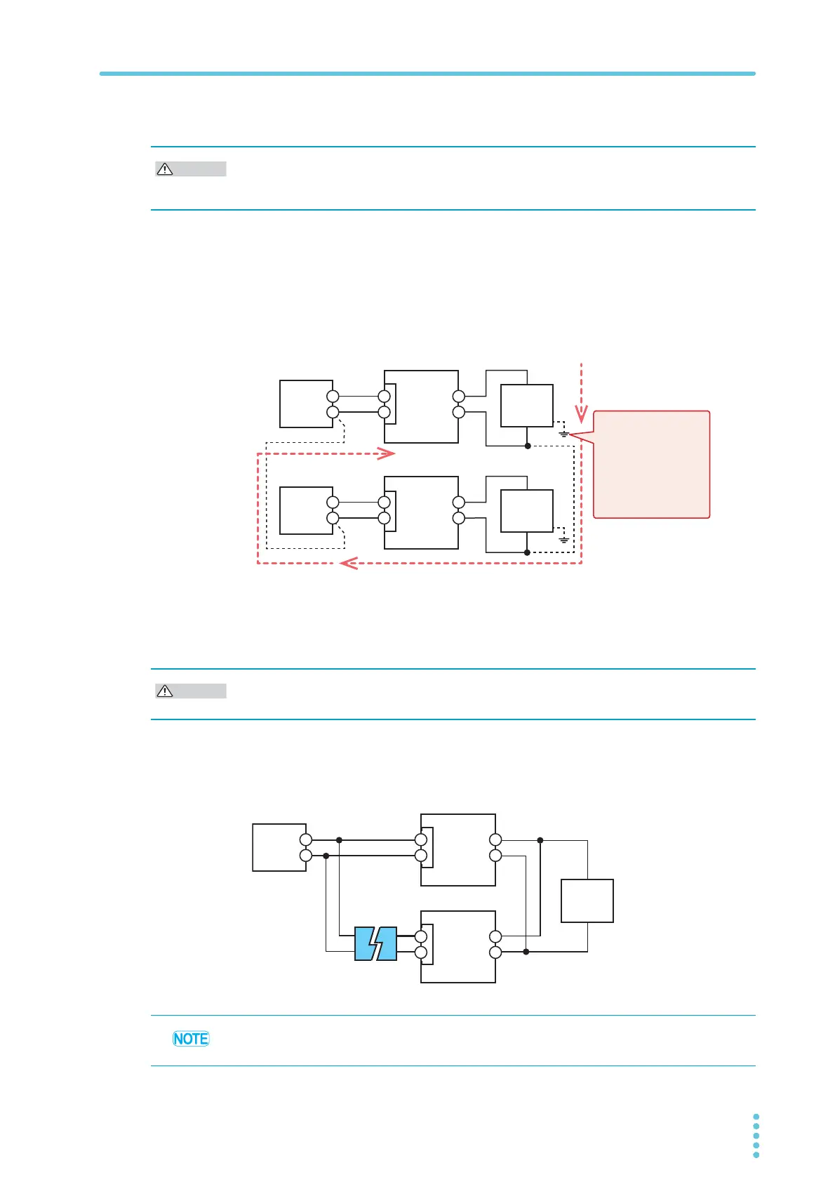
System that controls multiple PWR-01s with multiple Vexts
When the GND (negative) terminals between each Vext is connected ([1]), the path connect-
ing the A GND between each PWR-01 is formed. If you connect the negative output terminals
between each PWR-01, an unintended current loop shown in the following figure will be cre-
ated. This current loop may cause the system to malfunction or damage the devices.
In a system that controls multiple PWR-01s with multiple Vexts, such as that shown in the fol-
lowing figure, we recommend that you do not connect [1] and [2]. If you need to for systematic
reasons, connect either [1] or [2].
System that controls PWR-01s connected in parallel using a single
Vext
In a system that uses a single Vext to control PWR-01s connected in parallel, such as that
shown in the following figure, only a single PWR-01 can be connected directly to Vext through
a control cable. Connect other PWR-01s through isolators.
Connect the GND (negative) terminals between each Vext, but do not connect the negative
output terminals between each PWR-01. Not following this rule may cause the system to
malfunction or damage the devices.
PWR-01(B)
Vext2
[2]
[1]
+
–
+
–
+
–
+
–
A GND
J1
A GND
J1
Even when grounding
is established on the
EUT side, a path at
the ground potential is
formed like the
connection in [2], so
you need to be
careful.
Unintended current loop
Connect only a single PWR-01 directly to Vext through a control cable. Not following this rule
may cause the system to malfunction or damage the devices.
PWR-01(A)
+
–
+
–
A GND
J1
PWR-01(B)
+
–
A GND
J1
Load
(EUT)
The number of PWR-01s that can be connected directly is also one when using a system
that controls the output through an external contact using a sequencer or the like.