PWR-01 87
External Control | About the J1/ J2 Connectors
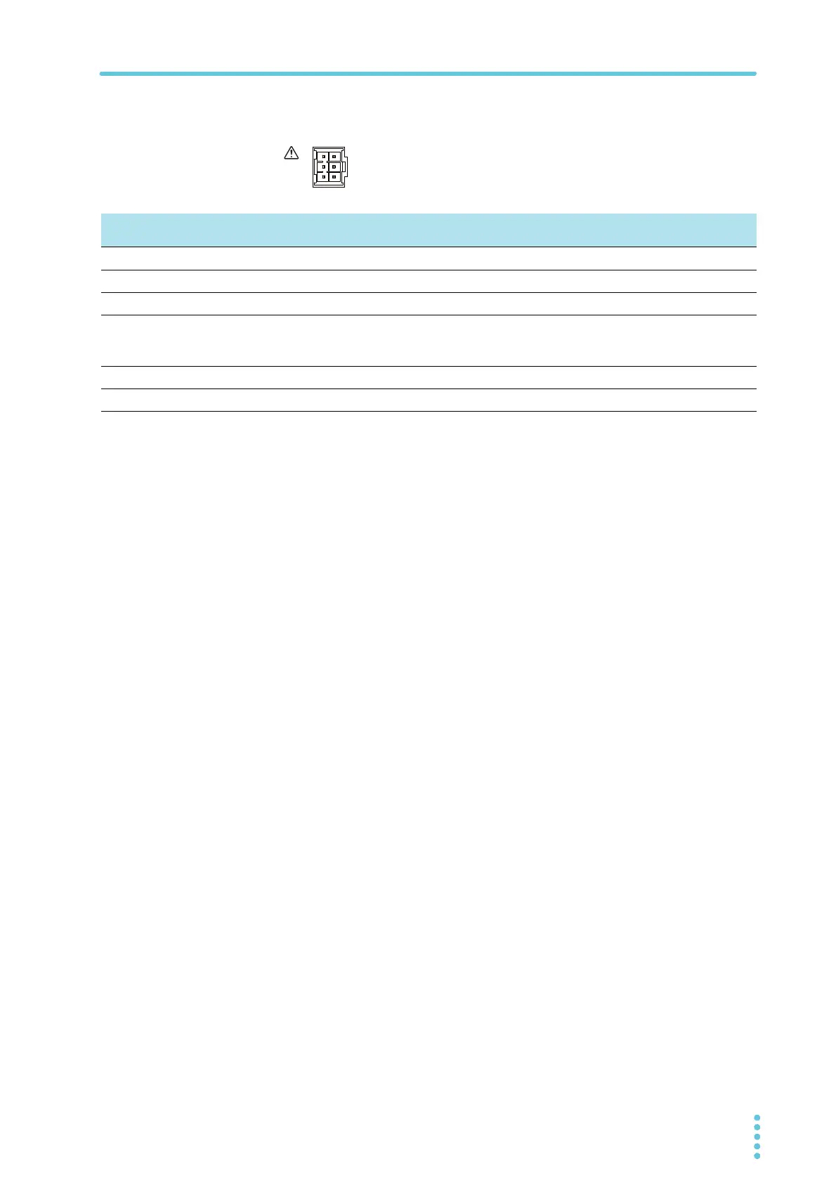
J2 connector pin arrangement
Pin number positions when you are facing the rear panel
Pin
No.
Signal name Description
J2-1 STATUS COM
Common for pins 2 to 6.
1
J2-2 OUT ON STATUS
Outputs a signal when output is on (output through an open-collector photocoupler).
2
J2-3 PWR ON STATUS
Outputs a low level signal when the power is on (output through an open-collector photocoupler).
2
J2-4 ALM STATUS Outputs a signal when a protection function (OVP, OCP, FOCP, OHP, SENSE, AC-FAIL) is activated
or when an output shutdown signal is being received (output through an open-collector photocou-
pler).
2
J2-5 CV STATUS
Outputs a signal during CV mode (output through an open-collector photocoupler).
2
J2-6 CC STATUS
Outputs a signal during CC mode (output through an open-collector photocoupler).
2
1 The status common is floating (isolation voltage of 800 V or less). It is isolated from the control circuit.
2 Open collector output:Maximum voltage: 30 V. Maximum current: 8 mA.