86 PWR-01
External Control | About the J1/ J2 Connectors
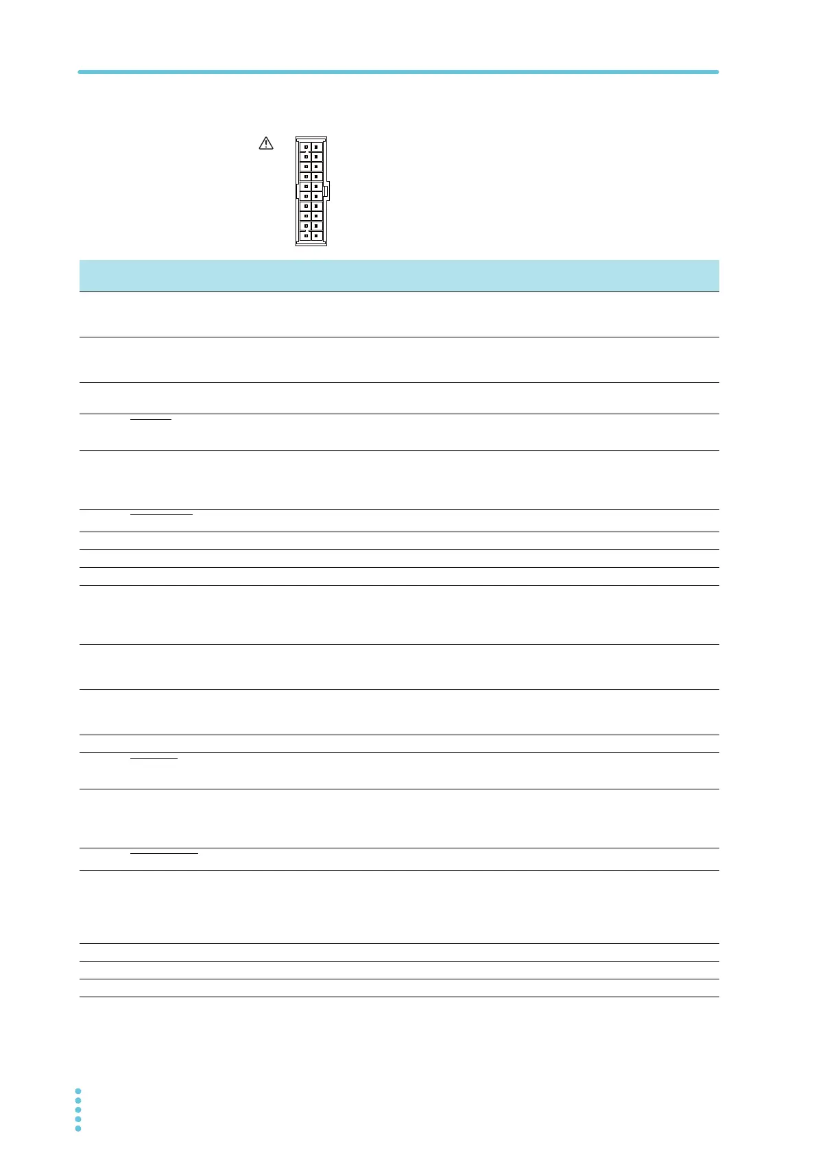
J1 connector pin arrangement
1
11
Pin number positions when you are facing the rear panel
Pin
No.
Signal name Description
J1-1 VPGM Terminal used to control the output voltage with an external voltage or external resistance.
0 V to 5 V; 0 % to 100 % of the rated output voltage (CF12: LO).
0 V to 10 V; 0 % to 100 % of the rated output voltage (CF12: HI).
J1-2 VMON Output voltage monitor.
0 % to 100 % of the rated output voltage is generated as a voltage between 0 V and 5 V (CF13: LO)
or a voltage between 0 V and 10 V (CF13: HI).
J1-3 REF OUT Reference voltage for external resistance control. 5.25 V (CF12: LO) / 10.5 V (CF12: HI), maximum
output current: 2.5 mA.
J1-4 PRL ON
On when parallel operation is in use and when output is on (output through an open-collector photo-
coupler).
J1-5 A GND External signal common for pins 1 to 3, 6 to 9, 11, 12, 14, 16, and 20.
When remote sensing is not used, this is at the same electric potential as the negative output termi-
nal. When remote sensing is used, this is at the same electric potential as the negative electrode (-S)
of sensing input.
J1-6 ALM CLEAR
Alarm clear terminal. Alarms are cleared when a low level signal (0 V to 0.5 V) is received or shorted.
J1-7 I SUM Current output terminal for parallel operation.
J1-8 PRL OUT Positive output terminal for parallel operation.
J1-9 PRL COMP IN Correction signal input terminal for parallel operation.
J1-10 A GND External signal common for pins 1 to 3, 6 to 9, 11, 12, 14, 16, and 20.
When remote sensing is not used, this is at the same electric potential as the negative output termi-
nal. When remote sensing is used, this is at the same electric potential as the negative electrode (-S)
of sensing input.
J1-11 IPGM Terminal used to control the output current with an external voltage or external resistance.
0 V to 5 V; 0 % to 100 % of the rated output current (CF12: LO).
0 V to 10 V; 0 % to 100 % of the rated output current (CF12: HI).
J1-12 IMON Output current monitor.
0 % to 100 % of the rated output current is generated as a voltage between 0 V and 5 V (CF13: LO)
or a voltage between 0 V and 10 V (CF13: HI).
J1-13 PRL COM Common for pin 4.
J1-14 PRL ALM
On when a protection function is activated during parallel operation or when an output shutdown sig-
nal is being received.
J1-15 A GND External signal common for pins 1 to 3, 6 to 9, 11, 12, 14, 16, and 20.
When remote sensing is not used, this is at the same electric potential as the negative output termi-
nal. When remote sensing is used, this is at the same electric potential as the negative electrode (-S)
of sensing input.
J1-16 SHUT DOWN
Output shutdown control terminal. The output is turned off when set to LOW (0 V to 0.5 V) or shorted.
J1-17 OUTPUT CONT Output on/off terminal.
On when set to LOW (0 V to 0.5 V) or shorted; off when set to HIGH (4.5 V or 5 V) or open
(CF15: LO)
On when set to HIGH (4.5 V to 5 V) or open; off when set to LOW (0 V or 0.5 V) or shorted
(CF15: HI)
J1-18 PRL COMP OUT Correction signal output terminal for parallel operation.
J1-19 PRL IN- Negative input terminal for parallel operation.
J1-20 PRL IN+ Positive input terminal for parallel operation.