PWR-01 99
External Control | External Monitoring
External monitoring of the operating status
The J2 connector has status outputs that can be used to externally monitor the operation sta-
tus of the PWR-01. The following five items make up the status outputs.
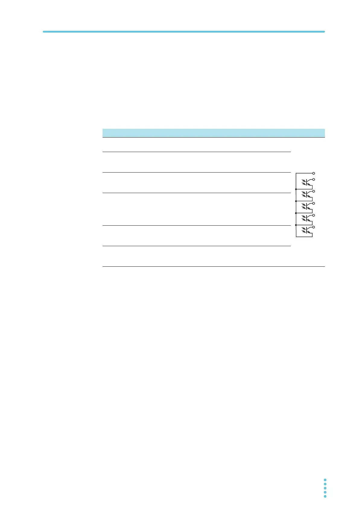
The outputs are open collector outputs of photocouplers; they are isolated from the internal
circuits of the PWR-01.
The status common is floating (that is, it has an isolation voltage of less than or equal to
800 V).
The maximum ratings of the signal terminals are as follows:
Maximum voltage: 30 V. Maximum current (sink): 8 mA.
Pin no. Signal name Description Circuit
J2-1 STATUS COM Status output common.
Photocoupler emitter output.
J2-2 OUT ON STATUS The level changes when the output is on.
LOW level (CF18: NEG), HIGH (CF18: POS)
Photocoupler open collector output.
J2-3 PWR ON STATUS This is set to low level when the POWER switch is
turned on (PWR ON STATUS).
Photocoupler open collector output.
J2-4 ALM STATUS The level changes when a protection function (OVP,
OCP, FOCP, OHP, SENSE, AC-FAIL) is activated or
when an output shutdown signal is received.
LOW level (CF19: NEG), HIGH (CF19: POS)
Photocoupler open collector output.
J2-5 CV STATUS The level changes in constant-voltage mode.
LOW level (CF17: NEG), HIGH (CF17: POS)
Photocoupler open collector output.
J2-6 CC STATUS The level changes in constant-current mode.
LOW level (CF16: NEG), HIGH (CF16: POS)
Photocoupler open collector output.
1
6
5
3
2