Service Manual
Operating Lights marLED® E3, E9, E9i, E15, battery and
marLED® E3 on ceiling tube Ø 110 mm
Revision 2 147
Resistance measurement 2
marLED® E9, E9i, E15 (battery)
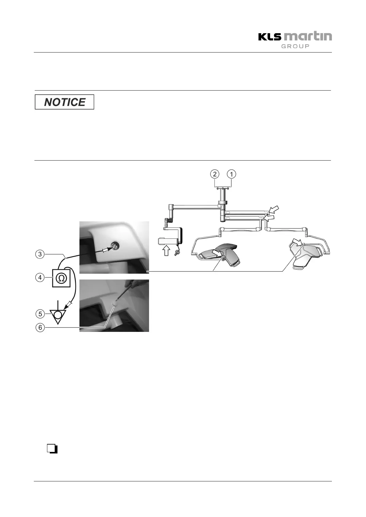
external protective conductor may only be used for measurement if the ceiling terminal is no longer
accessible (e.g. in the case of ventilated ceilings). However, this requires that both the measuring point
(5)
and the resistance between points
(2) and (5) were documented in the inspection plan at the time of
installation. These (first
-measured) values must be used as a reference basis for all subsequent
Central equipotential bonding terminal
Externally accessible protective conductor
• Remove the protective cap (6).
• Measure the resistance between the central equipotential bonding terminal (2) and the locations
indicated in the illustration, then note down the highest measured value in the inspection plan.
• In case of measurement via the external protective ground conductor (5), first measure the resistance
between the external protective ground conductor (5) and the location indicated in the figure, then
subtract the documented resistance between central equipotential bonding terminal (2) and external
protective ground conductor (5) from the highest measured value.
Enter the result into the inspection plan.
• √
 Loading...