Service Manual
Operating Lights marLED® E3, E9, E9i, E15, battery and
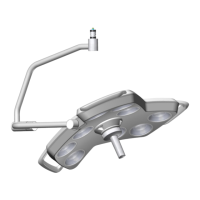
marLED® E3 on ceiling tube Ø 110 mm
Revision 2 47
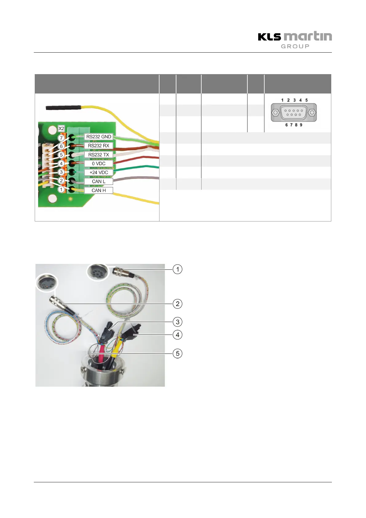
6.2.5 Pin Assignment X2 (CAN, RS232)
View of X2 Pin Color
Signal/
connection
Pin RS232 plug
7 GN RS232 GND 5
6 BN RS232 Rx 3
5 WH RS232 Tx 2
- YE The yellow lead of the RS232 cable is not used.
4 BN VDC- (0 VDC) supply
3 GN VDC+ (+24 VDC) supply
2 GY CAN L
1 YE CAN H
If the plug needs to be cut off the cable, the cables are connected inside the terminal block.
6.3 CAN Bus Cabling up to HW 09
Supply line coupler (5-pole)
If a wall control panel is included, it is connected
to coupler (2) of the cable projecting from the
ceiling tube using the 15-m connecting cable.
Fig. 6-2: CAN bus cabling (5) in arm system
 Loading...