Service Manual
Operating Lights marLED® E3, E9, E9i, E15, battery and
marLED® E3 on ceiling tube Ø 110 mm
34 Revision 2
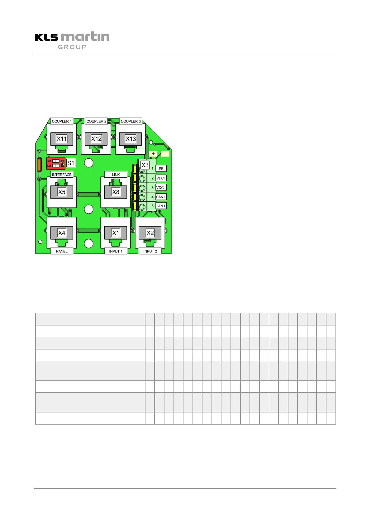
6.1.8 CAN Board with Galvanic Isolation
The CAN board for galvanic isolation connects the CAN conductors of the lights 2 to 4 to 3 separate RJ45
sockets. The connection to light 1 is made potential-free (galvanically isolated) in each case using a bus
coupler to be connected via a sufficiently long RJ45 cable. VDC+ is taken from light 1 (bottommost
position).
DIP switches for terminating resistor
Cable connection terminal block
LINK (connection of multiple CAN boards)
PANEL (marTouch®/wall control panel)
INPUT 2: Lights 3+4 (if configured)
To prevent mix-up, the connection points are
correspondingly marked (lettered) on the printed
circuit board.
6.1.9 Terminating Resistor S1 with Coupler
If at least one of the DIP switches of S1 is set to ON, the terminating resistor is switched on.
Possible combinations
Light 1 1 1 1 1 1 1 1 1 1 1 1 1 1 1 1 1 1 1 1 1
Light 2 1 1 1 1 1 1 1 1 - 1 1 - 1 1 - 1 1 - 1 1
Light 3 - 1 - 1 - 1 - 1 - - 1 - - 1 - - 1 - - 1
Camera on arm - - - - - - - - 1 1 1 1 1 1 1 1 1 1 1 1
Wall control panel/marTouch®
Presetting=1
- - 1 1 - - 1 1 - - - 1 1 1 - - - 1 1 1
RS232; Presetting=1 - - - - 1 1 1 1 - - - - - - 1 1 1 1 1 1
CAN board with galvanic isolation,
separate/on ceiling tube
0 0 0 0 0 0 0 0 0 0 0 0 0 0 0 0 0 0 0 0
Coupler; Presetting=1 1 1 1 1 1 1 1 1 1 1 1 1 1 1 1 1 1 1 1 1
Terminating resistor switched off
Terminating resistor switched on
 Loading...