Service Manual
Operating Lights marLED® E3, E9, E9i, E15, battery and
marLED® E3 on ceiling tube Ø 110 mm
32 Revision 2
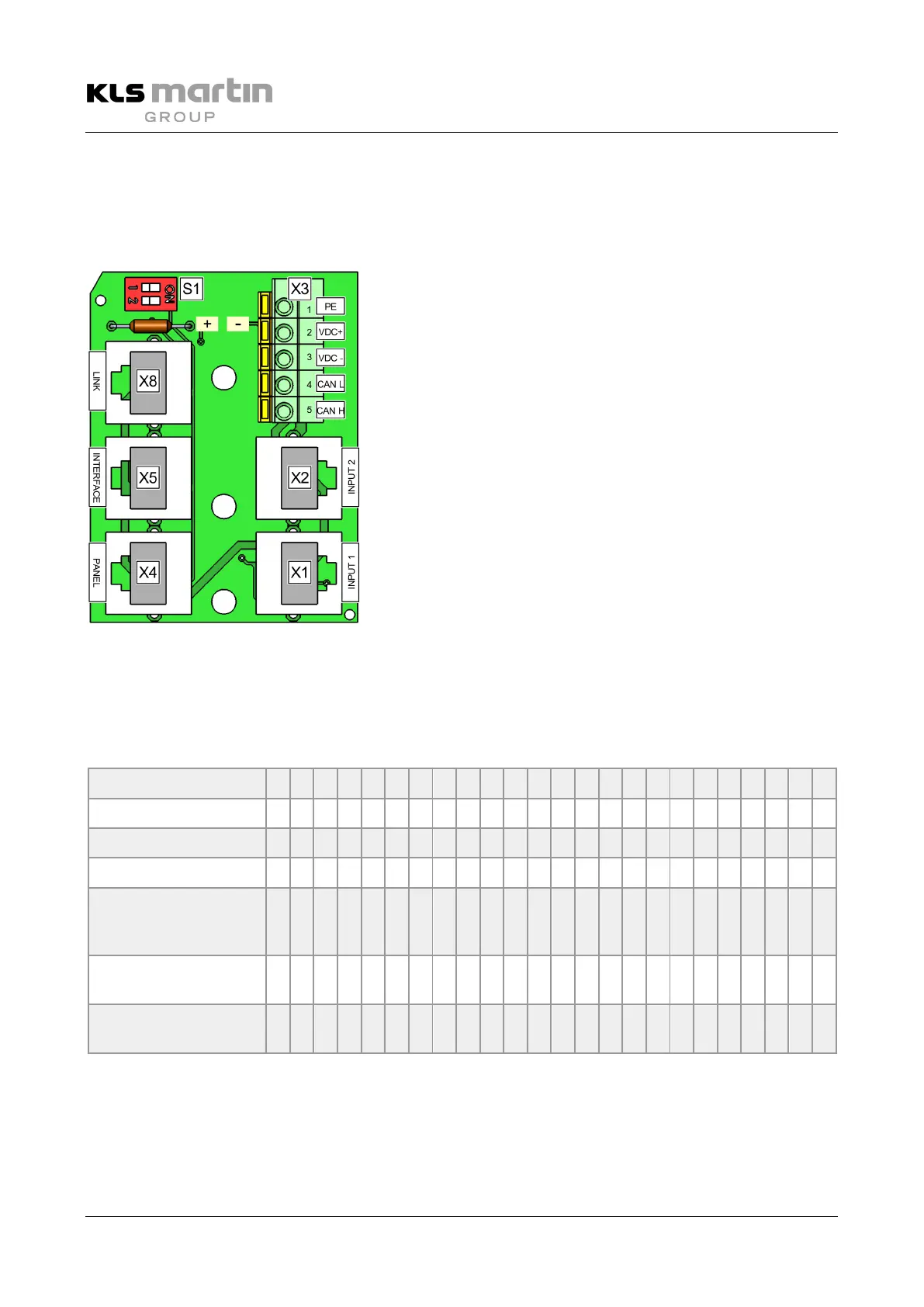
6.1.5 Standard CAN Board, no Galvanic Isolation
The standard CAN board connects the terminals VDC- of up to 4 lights, and CAN H and CAN L of all
populated RJ45 sockets (2–8).
VDC+ is taken from light 1 (bottommost position).
DIP switches for terminating resistor
LINK (connection of multiple CAN boards)
PANEL (marTouch®/wall panel)
Cable connection terminal block
INPUT 2: Lights 3+4 (if configured)
To prevent mix-up, the connection points are correspondingly
marked (lettered) on the printed circuit board.
6.1.6 Terminating Resistor S1 without Coupler
If at least one of the DIP switches of S1 is set to ON, the terminating resistor is switched on.
Possible combinations
Light 1 1 1 1 1 1 1 1 1 1 1 1 1 1 1 1 1 1 1 1 1 1 1 0 0
Light 2 - 1 1 - 1 1 - 1 1 - 0 0 - 1 0 - 0 0 - 0 0 - 0 0
Light 3 - - 1 - - 0 - - 0 - - 0 - - 0 - - 0 - - 0 - - 0
Camera on arm - - - - - - - - - - - 1 1 1 1 1 1 1 1 1 1 1 1
Wall control/
marTouch®
Presetting=1
- - - 1 1 1 - - - 1 1 1 - - - 1 1 1 - - - 1 1 1
RS232
Presetting =1
- - - - - - 1 1 1 1 1 1 - - - - - - 1 1 1 1 1 1
CAN board Standard,
separate/on ceil. tube
0 0 0 0 0 0 0 0 0 0 0 0 0 0 0 0 0 0 0 0 0 0 0 0
Terminating resistor switched off
Terminating resistor switched on
 Loading...