Do you have a question about the KLS Martin group marLED E3 and is the answer not in the manual?
Explains symbols for CAUTION, WARNING, DANGER.
Covers symbols for instructions, numbers, environmental conditions, and specific actions.
Details symbols for hazard classes, conformity marks, and high voltage warnings.
General safety precautions and warnings for document use.
Guidance for service personnel on performing work correctly and safely.
Definitions of technical terms and acronyms used in the manual.
Covers document validity, other applicable documents, and symbols used.
Provides a table mapping cable colors to their designations.
Provides information about the CE marking and the manufacturer.
Contact information for support and instructions for user inspection.
Outlines the terms and conditions related to product warranty and maintenance.
Specifies the intended application of the operating lights.
Details critical safety measures including electric shock, modification hazards, infection risks, and EMC compliance.
General safety, service work requirements, and inspection procedures.
Details personal safety measures, electric shock, explosion, weight, spring force, and service aid hazards.
Warns about the risk of unsecured screw connections loosening over time.
Warns about potential falling parts if screws are not tightened correctly.
Highlights the risk of premature wear if components are not greased regularly.
Explains the layout and rules for mounting positions of power modules on the ceiling tube.
Details available power module versions for standard and IT systems.
Provides circuit diagrams for systems with and without ASPS, and ASPS changeover function.
Instructions for adjusting the output voltage of the power supply.
Specific power supply details for the marLED® E3 model.
Details CAT wiring for the CAN bus system from hardware revision 30.
Specifies the CAT5 and TIA-568 B standards required for cables.
Provides the pin assignment according to the TIA-568 B standard for connectors.
Illustrates the circuit diagram for video cabling and CAN bus wiring.
Describes the CAN bus setup for a single ceiling tube without galvanic isolation.
Details the standard CAN board configuration and terminating resistor settings.
Explains how to set the terminating resistor S1 with and without a coupler.
Provides pin assignments for the cable connection terminal block X3.
Details the CAN board configuration with galvanic isolation.
Describes the CAN bus setup for a single ceiling tube with galvanic isolation.
Instructions for connecting bus couplers to the CAN board and power supply.
Details the pin assignments for the bus coupler connection board.
Provides troubleshooting steps for issues related to bus couplers.
Explains wall box rear and front connections, and marTouch® wall box pin assignments.
Explains how to connect COM interfaces to external control systems.
Shows COM interfaces for marLED® and surgiCam on ceiling tubes from HW 37.
Details COM interfaces for separate installation across different hardware revisions.
Provides the pin assignment for connector X2 (CAN, RS232).
Details CAN bus cabling for systems up to HW 09.
Presents an overview of the surgiCam HD camera system, cables, and connection options.
Explains DIP switches for setting CAN addresses and terminating resistors.
Details DIP switch SW6 settings for CAN addresses and system configuration.
Explains DIP switch SW1 settings for marLED® terminating resistors.
Details DIP switch SW1 settings for the surgiCam.
Describes CAN address assignment for lights from HW 30 and up to HW 09.
Covers procedures for replacing the contact block in the central bearing shaft.
Details tracking arm and ceiling tube connections, circuit diagrams, and RJ45 pin assignments from HW 30.
Explains circuit diagrams and connections for tracking arms up to HW 09.
Explains CAT cabling for video signals from HW 30.
Provides instructions for video cabling to monitors, including NDS monitor descriptions.
Details video cabling connections to the wall box.
Illustrates cabling for the surgiCam wall box.
Details cabling procedures for the NDS ScaleOR with wall boxes.
Explains video cabling routes to the monitor and then to the wall box.
Covers safe dismounting and reinstallation of the light head, including height stop adjustment.
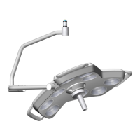
Provides an overview and identification of components within the marLED® E3 light head.
Explains the service plug and preparatory steps before accessing the light head.
Instructions for disconnecting, connecting, replacing, and managing battery packs.
Covers removing/installing light engines, gasket, control panel foil, and opening/closing the housing.
Details mounting the surgiCam daughterboard and replacing control electronics.
Procedures for replacing the cardanic suspension, including safety warnings.
Guidance on installing light engines, including variants and types.
Covers connecting wall control panels from different hardware revisions (HW 37, HW 30-36, up to HW 35).
Describes accessing and adjusting parameters for switching between Modbus and Serial control.
Lists and explains error messages displayed on the wall control panel.
Shows wiring diagrams for wall control panels and surgiCam systems up to HW 09.
Covers control electronics board design with miniature fuses across different hardware versions and voltage measurement.
Details pin assignments and circuit diagrams for light engines from HW 40 and up to HW 39.
Shows cable harness connections from control electronics to marLED® E9(i) and E15 light engines.
Describes control panel foils from HW 32 and up to HW 31, including functions, modes, and circuit diagrams.
Details the scope of delivery for the marLED® E interface adapter.
Information on using and installing the USB serial adapter and its drivers.
Covers installing C2Prog, connecting the adapter, and programming master, slave, and camera daughterboards.
Details how to set color temperature and light field size using sensoGrip or control panel.
Addresses troubleshooting, error messages, parameters, and common error patterns with solutions.
Explains how to identify master and slave channels for diagnosing LED malfunctions.
Details inspection notices, inspection plan requirements, and safety precautions during maintenance.
Provides instructions for performing various system checks, including torque, alignment, and resistance measurements.
Instructions for checking and securing fixing screws on the tracking arm system.
Instructions for checking the presence and fixing of safety sleeves.
Details checking and securing locking screws for AC2000 LC and Onda Space LC systems.
Instructions for checking and replacing worn locking segments on various spring arm systems.
Procedures for checking bearings and adjusting brake screws on arm systems.
Guidance on checking and replacing defective end stops on spring and tracking arms.
Instructions for checking spring arm settings, rating plates, and warning labels.
Details checking contacts in the tracking arm and cover panels for secure attachment.
Procedures for checking light head for damage, seals, sensoGrip, and light engines.
Covers checking monitor seat, TFT bracket, and connections on monitor suspension systems.
Covers checks for emergency power, function tests, light field, color temperature, and COM interface operations.
Instructions for measuring illuminance and supply voltage on contact blocks.
Explains the structure and meaning of characters in the serial number.
Details the structure and information provided in the surgiCam serial number.
Lists software updates, their dates, and descriptions of changes made to the system.
Details hardware revisions, their dates, and the nature of the changes implemented.
Outlines regulations for transporting hazardous goods, including lithium-ion batteries.
Provides guidance on the proper disposal of the device and packaging according to regulations.
Provides detailed technical specifications for marLED® E9 and E9i lights across different hardware versions.
Lists technical data for marLED® E9 and E9i battery-powered lights.
Provides detailed technical specifications for marLED® E15 lights across different hardware versions.
Lists technical data for marLED® E15 battery-powered lights.
Provides detailed technical specifications for marLED® E3 lights.
| Color Rendering Index Ra | 95 |
|---|---|
| Focusable | Yes |
| LED Lifetime | 50, 000 hours |
| Light Source | LED |
| Warranty | 2 years |
| Color Temperature | 4500K |
| Power Supply | 100-240 V, 50/60 Hz |