Service Manual
Operating Lights marLED® E3, E9, E9i, E15, battery and
marLED® E3 on ceiling tube Ø 110 mm
52 Revision 2
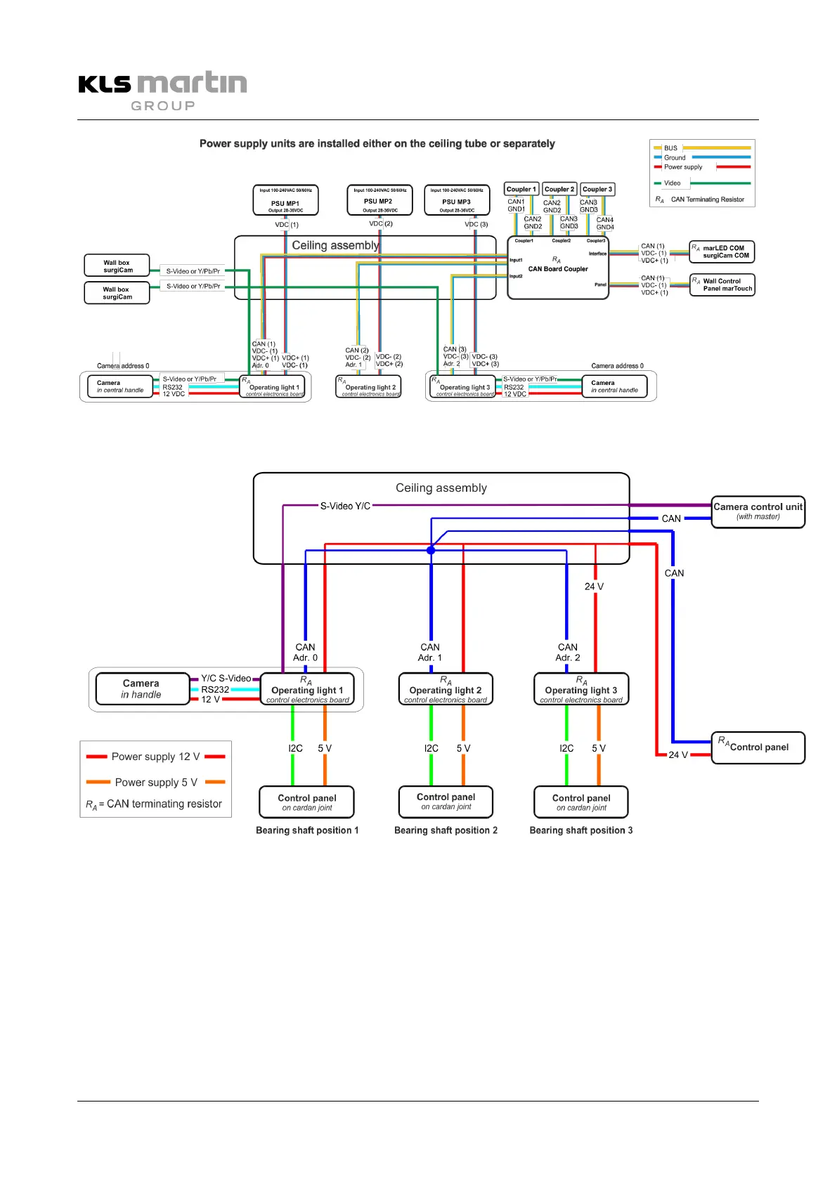
Fig. 6-4: Data communication in marLED® light system, wiring with galvanic isolation from HW 30
6.4.6 Setting of the CAN Addresses up to HW 09
Fig. 6-5: Data communication in marLED® light system, wiring up to HW 09
The color temperature of all connected lights (5-pin or 9-pin cabling) is synchronized via the CAN bus.
The wall control panel is controlled via CAN bus. The CAN bus occupies the leads CAN H, CAN L. Camera
control, e.g. zoom, also takes place via the CAN bus of the light system.
If a wall control panel is included, its connecting cable (15 m) is connected to the 5-pole socket, see
section 7.3.1 “Circuit Diagram for 5-Pole Tracking Arm with Wall Control Panel”, page 62.
 Loading...