Service Manual
Operating Lights marLED® E3, E9, E9i, E15, battery and
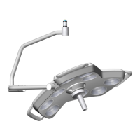
marLED® E3 on ceiling tube Ø 110 mm
Revision 2 33
Rules for setting the terminating resistor
The terminating resistor should be set to ON for the two CAN bus users farthest apart from each
other.
Only one terminating resistor may be switched on for each light. For marLED® E lights with surgiCam,
the marLED® terminating resistor must be switched off and only the terminating resistor of the
surgiCam daughterboard is switched on according to table, see section 6.4.4 “DIP switch SW1
surgiCam”, page 51.
The terminating resistor of a surgiCam COM interface must always be set to ON.
The terminating resistor of a marLED® COM interface may only be set to ON if no surgiCam COM
interface is included in the configuration.
The terminating resistor of the standard CAN board is normally set to OFF. In exceptional cases, e.g. if
long cables are used, point-to-point termination can be required (resistor switched on).
Once all devices are connected, the resistance between CAN
L and CAN H must range between 40 and
Ω to ensure perfect CAN bus functioning.
Long cables can additionally increase the measured resistance value.
Prior to each resistance measurement, make sure that the system is fully wired and off-circuit. If not,
the measured resistance value is useless.
6.1.7 Pin Assignment of Cable Connection Terminal Block X3
The terminal block X3 is used to connect a control panel whose RJ45 plug had to be cut off during the
mounting process (marTouch®, COM interface, wall box, wall control panel). Note that conductor cross-
sections must not be less than 0.3 mm
2
(AWG22) for proper connection.
The pin assignment of this terminal is identical for both CAN board types:
Pin Signal Cable color(s) TIA-568 B
1 PE -
2 VDC+ BU + BNWH
3 VDC- (light 1) BN + BUWH
4 CAN H 1 GNWH
5 CAN L 1 GN
 Loading...