Service Manual
Operating Lights marLED® E3, E9, E9i, E15, battery and
marLED® E3 on ceiling tube Ø 110 mm
Revision 2 37
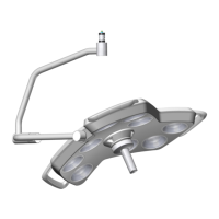
6.1.11 Connecting the Bus Couplers to the CAN Board
If more than one light has been connected, a bus
coupler must be used in each case to connect the
remaining lights to light 1:
• Bus coupler 1 at X11 for light 2
• Bus coupler 2 at X12 for light 3
• Bus coupler 3 at X13 for light 4
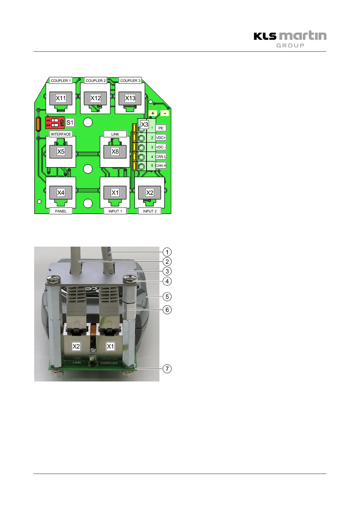
6.1.12 Connecting the Bus Couplers to the Power Supply
• Connect the PSU of the coupler (5) to the mains
power supply (100–240 VAC).
• Unscrew the 2 screws (4) to remove the cover
plate (3) of the RJ45 plugs from the spacers (6).
• Plug the RJ45 cable (1) leading to the
CAN board (7) into the RJ45 socket X1 (COUPLER).
• If more than one ceiling tube is included in the
configuration, use the second RJ45 socket
X2 (LINK) to connect additional bus couplers (2).
• Put the cover plate (3) of the RJ45 plugs back in
place using the screws (4).
The cover plate (3) must be fixed in place to prevent both the connection of third-party plugs and the
accidental removal of installed plugs.
Once the bus couplers have been configured correctly, the process of establishing a potential-free
(electrically isolated) CAN connection between the lights is complete.
 Loading...