11.4.3 Recommended cable type
max.
length
recommended cable @ amplifier rated output current
Purpose In=1.5...10A In=14...24A In=40...70A
AC-supply* - H07V-K 1.5 H07V-K 4 H07VVC4-K 3G 25
DC-bus link* 0.5 m H07V-K 1.5 H07V-K 4 H07V-K 25
2m H07VVC4-K 2X 1.5 H07VVC4-K 2X 4 H07VVC4-K 2X 25
Ext. brake resistor* 5m H07VVC4-K 2G 1.5 H07VVC4-K 2G 25
* valid only for single-axis systems. For multi-axis systems, please consult our customer support.
11.4.4 Preparing cables for AKD/S300/S400/S601...620/S700
The connections are located on the bottom or front of the servo amplifier. Terminal con-
nectors are used, which are included in the delivery package for the servo amplifier. The con-
nectors are coded and have the appropriate connection designation printed on them. They
must never be mixed up.
Follow the pin assignment in the instructions manual. When connecting an external brake res-
istor, please note that the link cable must first be removed.
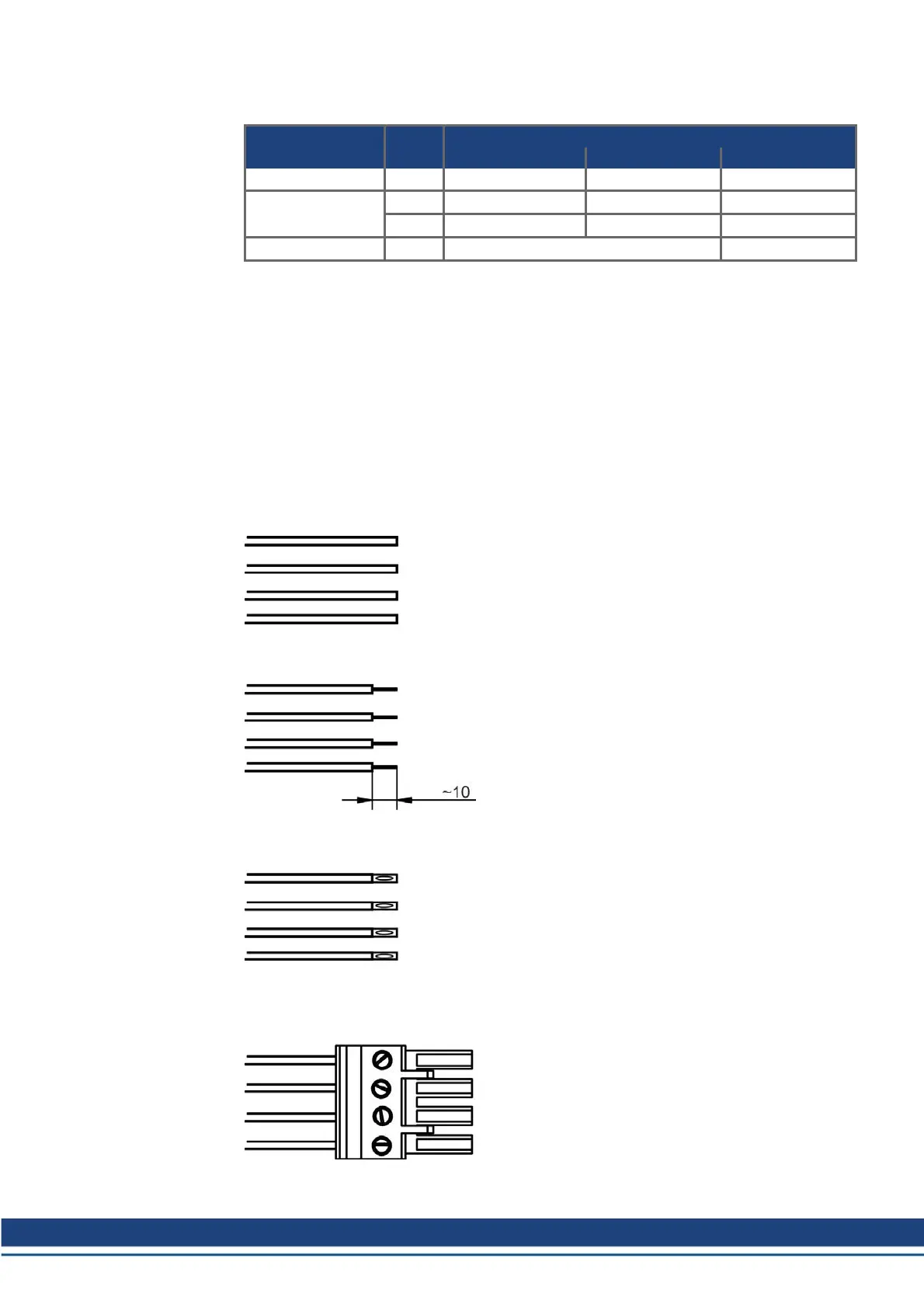
Preparing unshielded cables
If shielding is not necessary, then we recommend using single cores for the wiring inside the
switchgear cabinet.
Strip off about 10 mm of the insulation at the ends of the
cores. Take care to avoid damage to the copper strands
while doing this. Depending on the cross-section of the
core and the type of bootlace ferrule that is used, the
length that has to be stripped may vary by several mil-
limeters.
Apply bootlace ferrules to the conductors. As an altern-
ative, you can also use terminal pins.
Connector example S600:
Push the ends of the conductors into the connector as far
as they will go. Follow the pin assignment in the servo
amplifier's instructions manual. Tighten the screws of the
terminals. Take care that the insulation is not trapped in
the terminals.
Accessories Europe | 11 Cables
Kollmorgen | December 2014 49
 Loading...


