11.11.3 Preparing motor cables (motor end)
11.11.3.1 Motor series AKM2...8, 6SMx7, DBL2...6, DBK
Motors with connectors should be connected with our pre-assembled cables.
11.11.3.2 Motor series AKM8, DBL7/8
These motors are fitted with terminal boxes, in which there are bolts or terminals for con-
nections. The terminal boxes have 2 screw glands, so that the power and brake cables can
be routed separately. If a motor cable with integral brake is used, the unused screw gland
must be replaced by a blanking plug. Please refer to the instructions manual for the motor
series.
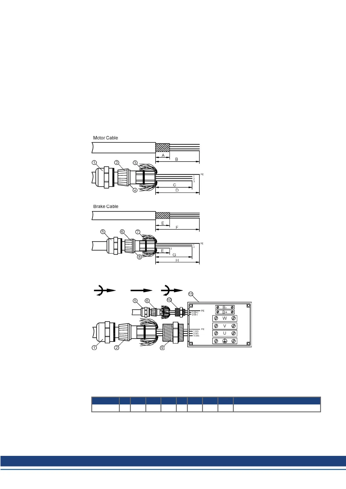
Preparing cables for terminal box, separate cables (DBL7/8)
Remove the outer covering
over length B, without dam-
aging the shielding braid.
Shorten the shielding braid
to length A.
Push the union nut (1) and
the clamping ring (2) onto
the cable and push the
shielding braid back over
the clamping ring. The
shielding braid must cover
the sealing ring (3), but must
not stick out over the sealing
edge (4). Cut off the cores to
lengths C and D.
Remove the outer covering
over length F, without dam-
aging the shielding braid.
Shorten the shielding braid
to length E.
Push the union nut (5) and
the clamping ring (6) onto
the cable and push the
shielding braid back over
the clamping ring. The
shielding braid must cover
the sealing ring (7), but must
not stick out over the sealing
edge (8). Cut off the cores to
lengths E/G/H. Remove the
insulation from core 3 and
lay it over the shielding
braid.
Screw the threaded sleeve (9) or (10) into the terminal box (11, example: AKM8 Motor). Push
the cores of the cables and the clamping rings (2) or (6) through the threaded sleeve and
screw the union nut (1) or (5) tightly onto the threaded sleeve. Then fit bootlace ferrules or ter-
minal pins to the ends of the cores for the brake connections, and ring terminals to the power
connections and the PE.
Motor A B C D E F G H Connection
DBL7/8 20 140 110 140 20 140 130 140 Terminals (similar to drawing)
Accessories Europe | 11 Cables
Kollmorgen | December 2014 75
 Loading...


