11.7 Encoder Emulation, Stepper motor control, Master-Slave
This interface can be used for several applications (see the amplifiers instructions manual).
The material requirements are always the same.
We do not deliver configured cables for this interface.
11.7.1 Mating connector, cable type
Article Description Order Code
Cable 4x2x0.25 (per meter) DE-92186
Sub-D connector kit Socket 9-pole, housing and screws DE-81784
Connector kit, amplifier
end AKD-B/P/T/M, X9/X10
X10 male connector 15 pin high density, X9
female connector 9 pin, 2 housings, screws
AKD-X9+X10-Kit
11.7.2 Connection
The cable used must be shielded, with twisted pairs to (suggestion according to DIN 47100).
Since it is important which signal pairs are twisted together, the following table shows the col-
ors of the individual cores (to IEC 60757).
SubD9 SubD9, X9 Core color @ 5x2x0.25
S300...S700 AKD-B/P/T/M ROD SSI, Stepper motor control, Master-Slave
1 3 WH WH
2 7 GN n.c.
3 8 YE n.c.
4 1 GY GN
5 2 PK YE
6 4 BU GY
7 5 RD PK
8 n.c. 6 BK BK
9 n.c. 9 BN n.c.
The connector assignment is determined by the use of the interface; see the servo amplifier
instructions manual.
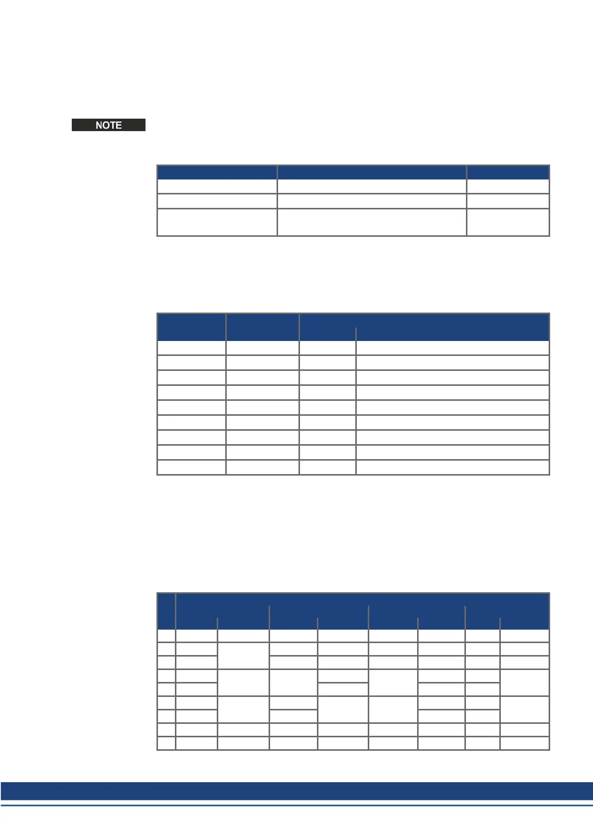
11.7.3 Termination resistors
Depending on servo amplifier type (see instructions manual for the servo amplifier) and
application, the cable must be terminated by termination resistors at the amplifier end or the
control end. The resistance values depend on the characteristic impedance of the cable
material.
Interface function (S300/S400/S600/S700)
ROD SSI Stepper control Master-Slave
Pin Amplifier Controller Amplifier Controller Amplifier Controller Master Slave
1 - - - - - - - -
2 -
R ~ 150Ω
- - - - - -
3 - - - - - - -
4 -
R ~ 150Ω R ~ 150Ω
-
R ~ 150Ω
- -
R ~ 150Ω
5 - - - -
6 -
R ~ 150Ω
-
R ~ 150Ω R ~ 150Ω
- -
R ~ 150Ω
7 - - - -
8 - - - - - - - -
9 - - - - - - - -
Accessories Europe | 11 Cables
Kollmorgen | December 2014 57
 Loading...


