Accessories Europe | 11 Cables
11.11.4.5 Preparing cables for AKD-x01206/X02406/X0xx07
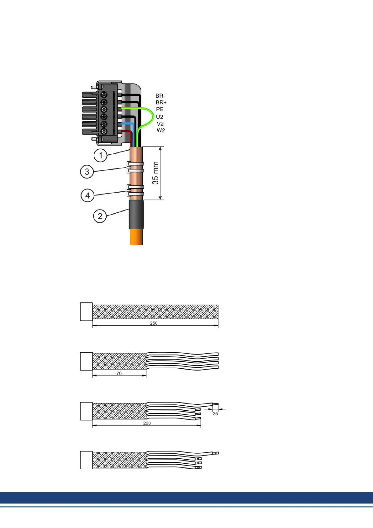
The motor is connected to the AKD-x01206/x02406/x0xx07 by a Power Combicon connector
(➜ p. 77). You can obtain the connector kit from us (with connector, housing, shield plate,
rubber bushes, installation material).
Strip the external cable sheath to a length of approx.
120 mm, taking care not to damage the braided
shield. Push the braided shield (1) back over the
cable and secure with a rubber sleeve (2) or shrink
sleeve.
Shorten all the wires apart from the protective earth
(PE) wire (green/yellow) by about 20 mm so that the
PE wire is now the longest wire. Strip all wires and fit
wire end ferrules.
Secure the braided shield of the cable to the shroud
with a cable tie or a hose clamp (3) and use a
second tie (4) to fasten the cable.
Wire the connector as shown in the connection dia-
gram. Plug in the connector to the socket on the front
of the AKD.
Screw the connector in place. This ensures that
there is conductive contact over a large surface area
between the braided shield and the front panel.
11.11.4.6 Preparing cables for S640/670 and S748/772
Motor Power Cable
The motor is connected to the S640/670 or S748/772 by terminals. The cable material
depends on the motor that is used. Please refer to the instructions manual for the cor-
responding motor series.
Please take note that the terminals can
accept a core cross-sections of 10 to
50mm².
Remove the outer covering over a
length of 250 mm, without damaging
the shielding braid.
Shorten the shielding braid to a length
of 70 mm.
Shorten the cores for the power con-
nections to 200 mm. Strip off about
25mm of the insulation from all cores.
The length varies with the conductor
cross-section and the type of bootlace
ferrule that is used.
Apply bootlace ferrules to the con-
ductors. Do not use terminal pins,
because their cross-section is too
small.
80 Kollmorgen | December 2014
 Loading...


