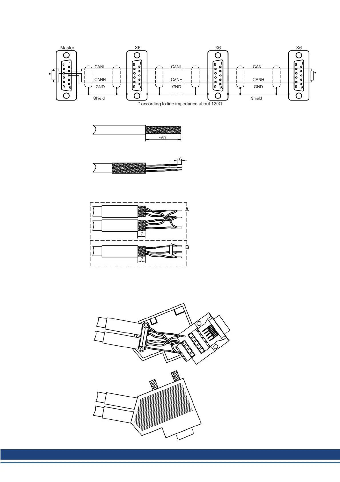
Wiring diagram
Preparing cables
Remove the outer covering of the
cable over a length of about 60mm,
without damaging the shielding
braid.
Push the shielding braid back over
the outer covering of the cable, and
strip off the ends of the cores over a
length of about 7 mm, without dam-
aging the copper strands. The
length can vary according to the
type of bootlace ferrule that is used.
Push a suitable piece of heat-shrink
tubing over the outer cover, and
heat it up. Leave about 7mm free at
the end. Fit appropriate bootlace fer-
rules to the cores. Depending on
which type of connector you are pre-
paring, use diagram A (inner bus
connector), or B (outer bus con-
nector). Use ferrules for twin wires if
you have to connect two cores, or
one core and a termination resistor
to a single connection.
Use the strain relief to fix the cable
to the bottom half of the housing. Do
not overtighten the screws, or the
cable will be crushed. Wire up the
terminals according to the wiring
diagram, and place the connector
PCB with the terminals underneath
in the lower half of the housing.
Put the two knurled screws in place,
and press the two halves of the
housing together until the four lugs
snap into position.
Take care that the connector PCB
and the knurled screws are properly
located.
Accessories Europe | 11 Cables
Kollmorgen | December 2014 61
 Loading...


