COMPLETE ASSEMBLY TRANSMISSION
7C - 23
1. Transmission Case 12. Countershaft Cover 23. Scavenge Tube Baffle
2. Rear Cover 13. Port Plug 24. Main Regulator Valve
3. Directional (Input) Shaft 14. Reverse Idler Gear 25. Range Selector Valve
4. Tapered Roller Bearing 15. Range (Output) Shaft 26. Rate of Rise Valve
5. Directional Shaft Manifold 16. Tapered Roller Bearing 27. Valve Gasket
6. Dowel Pin 17. Tapered Roller Bearing 28. Orifice Strainer
7. Seal Ring 18. Range Shaft Manifold 29. Valve Manifold
8. Shim 19. Seal Ring 30. Manifold Gasket
9. Retaining Ring 20. Shim 31. Scavenge Tube
10. Oil Seal 21. Retaining Ring 32. Scavenge Tube Gasket
11. Countershaft 22. Adapter Fitting
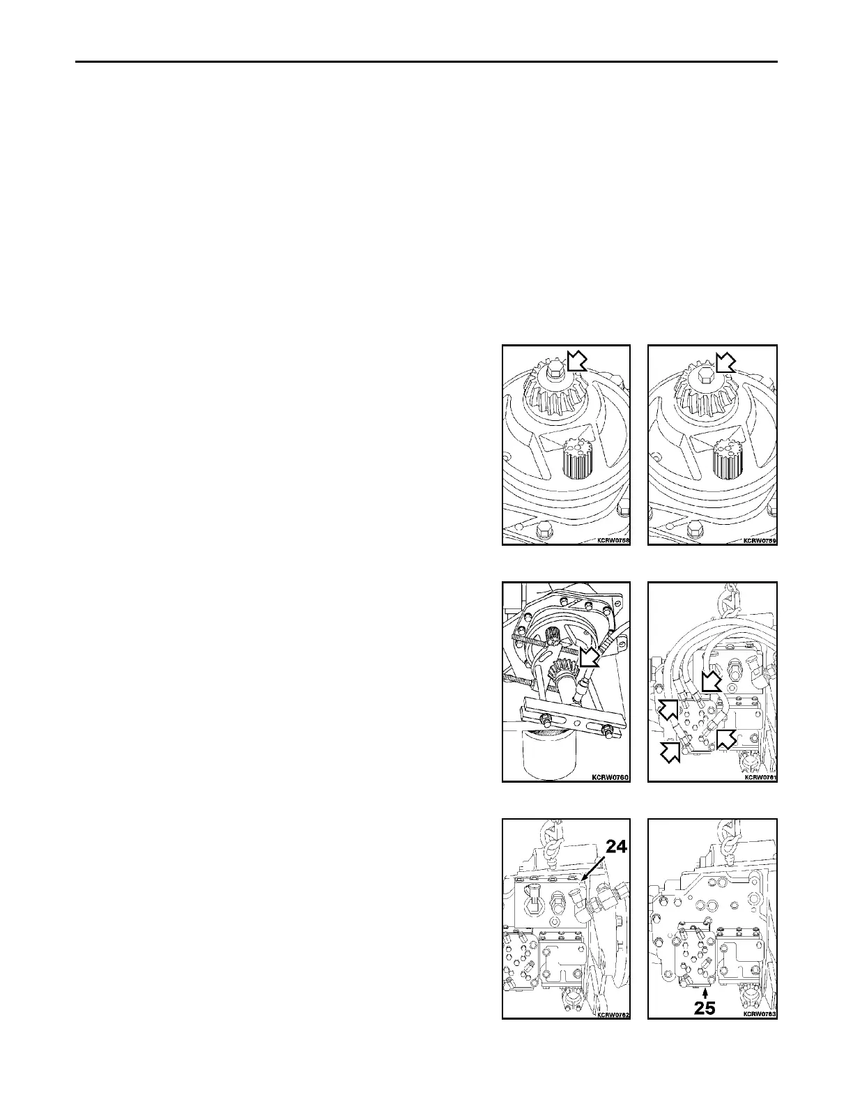
DISASSEMBLY
REMARK
Callouts from exploded view correspond with callouts in the
following steps.
1. D32E-1, D32P-1, D38E-1 or D38P-1: Remove mounting bolt
and spacer securing pinion gear to output shaft.
1. D39E-1 or D39P-1: Remove mounting bolt and spacer securing
pinion gear to output shaft.
2. Remove pinion gear from output shaft. A puller arrangement
may be necessary to remove gear.
3. Remove four hoses at range selector valve (25).
4. Remove main regulator valve (24). Discard two large and two
small mounting o-rings. Refer to MAIN REGULATOR VALVE for
service.
5. Remove range selector valve (25). Remove and discard ten
mounting o-rings. Refer to RANGE SELECTOR VALVE for
service.
 Loading...


