FINAL DRIVE REASSEMBLY
7F - 20
22. D32E-1 or D38E-1: Assemble two ¾NF bolts in opposite holes
of sprocket carrier shaft (2). Position pry bar to prevent shaft
rotation. Torque sprocket carrier shaft retainer bolt to 305 NCm
(225 lbf ft).
D32P-1 or D38P-1: Assemble two ¾NC bolts in opposite holes
of sprocket carrier shaft (2). Position pry bar to prevent shaft
rotation. Torque sprocket carrier shaft retainer bolt to 305 NCm
(225 lbf ft).
Now remove longer bolt and two carrier washers. Install bolt (9)
and torque to 475 NCm (350 lbf ft).
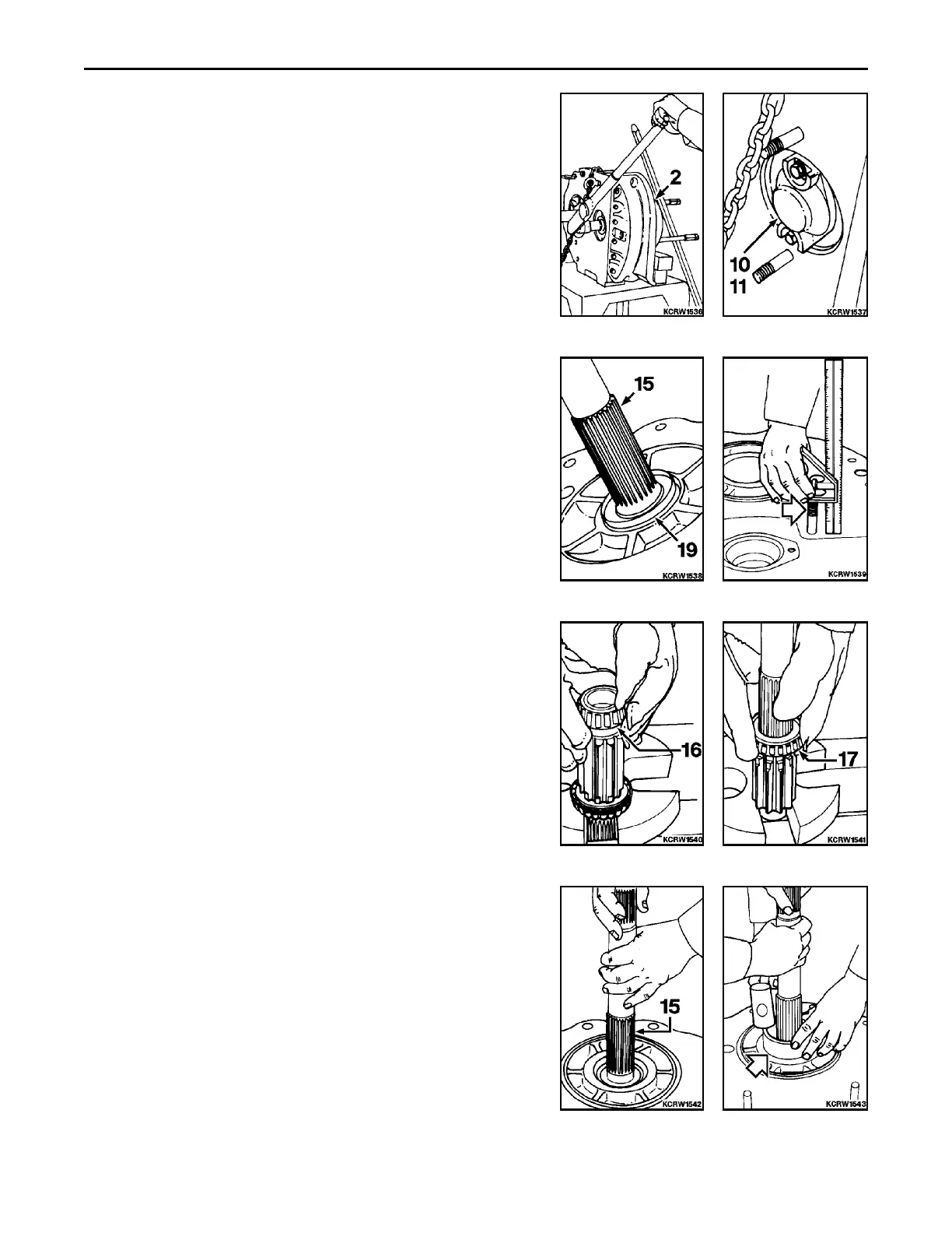
24. Assemble carrier shaft cover (11) and gasket (10). Secure with
hardware. Torque bolts to 60 NCm (45 lbf ft) ±10%.
25. Carefully work shaft oil seal (19) (spring garter facing out) down
pinion shaft (15), being careful not to cut sealing lip surface.
Using a suitable driver, press pinion shaft seal edge flush with
shoulder.
D39E-1 OR D39P-1
REMARK
Callouts from exploded view correspond with callouts in following
steps.
1. Block final drive housing in a horizontal position with rear main
frame mating face up. Check height of two mounting studs for
65 mm (2.56 in) dimension. If necessary to install new studs,
apply Loctite #568 or Plastic Gasket before installing. If neces-
sary, assemble pinion shaft outer bearing cup (16) to housing.
Using a driver, tap to seat in housing.
2. Heat pinion shaft outer bearing (16) to 135EC (275EF) for 45
minutes and assemble to shaft. Tap to seat against shoulder of
shaft.
3. Invert shaft. Heat pinion shaft inner bearing (17) to 135EC
(275EF) for 45 minutes and assemble to shaft. Tap to seat
against shoulder of shaft.
4. Prelube pinion shaft bearings and set shaft (15) into outer
bearing cone.
5. Using driver, install inner bearing cup, while rotating shaft, until
a slight resistance to rotation is felt.
 Loading...


