TRANSMISSION MAIN REGULATOR VALVE
7C - 84
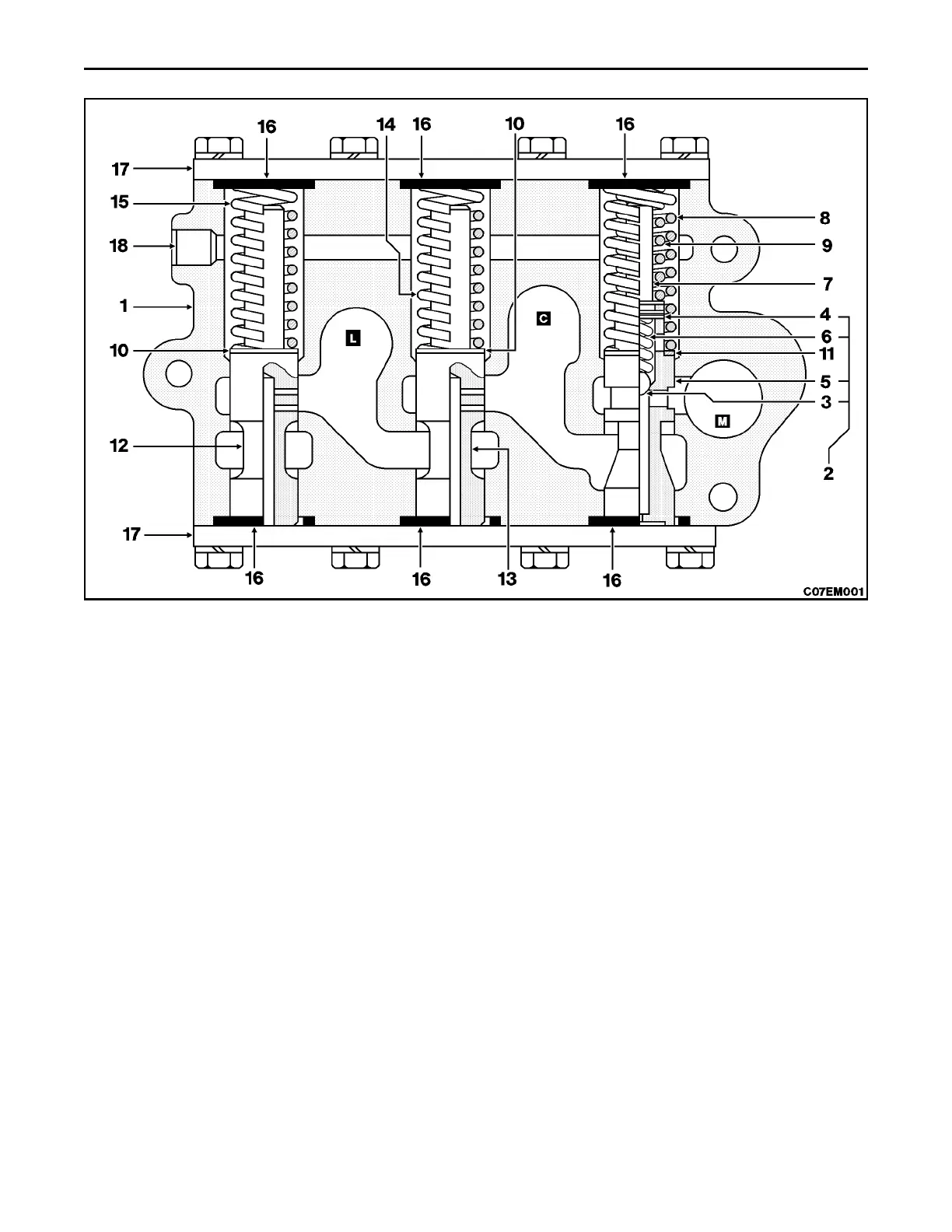
CROSS SECTION VIEW OF MAIN REGULATOR VALVE
1. Valve Housing 6. Check Ball Spring 11. Main Spool Shim 16. O-Ring
2. Main Spool Assy 7. Spring Guide Pin 12. Lube Spool 17. End Cover
3. Check Ball 8. Main Outer Spring 13. TC Spool 18. Port Plug
4. Spring Pin 9. Main Inner Spring 14. TC Spool Spring
5. Main Spool 10. Spool Shim 15. Lube Spool Spring
DESCRIPTION
This valve is a cascade type, pressure control valve consisting of three individual valves encased in one housing. The
first valve is used to control pressure for engagement of the clutches in the transmission and the steering drive. The
second valve is used to control pressure in the torque converter. The third valve is used to control lube pressure in the
transmission. A cold oil relief valve is included in the first valve.
THEORY OF OPERATION
Oil from the pump enters the valve at cavity M. This oil is then directed through the other control valves and on to the
transmission and steering drive to operate the clutch packs. As pump flow continues, pressure builds and oil is forced
through the center of spool (5), causing the spool to move against the outer and inner springs (8 and 9). When the
pressure reaches 1792 to 1930 kPa (260 to 280 psi) the first valve opens and allows oil to enter cavity C. The main
spool also contains a cold oil relief valve. When the oil is cold pressure can exceed 1930 kPa (280 psi). When this hap-
pens, the check ball (3) is forced against the spring (6) and excessive pressure is relieved and valve chatter is prevented.
Excessive oil from cavity M enters cavity C and is directed on to the converter. When flow requirements for the converter
is met, pressure builds and oil is forced through the center of the spool (13) causing the spool to move against the spring
(14). When pressure reaches 483 to 655 kPa (70 to 95 psi) in neutral or in gear, the second valve opens and allows
oil to enter cavity L. Return oil from the oil cooler and excessive oil from cavity C enters cavity L and is then directed to
the transmission for lube. Whenever this lube oil reaches 172 to 241 kPa (25 to 35 psi) in neutral or 138 to 206 kPa (20
to 30 psi) in gear, the third valve opens and dumps the oil to drain.
 Loading...


