ANGLING FRAME MOUNTED EQUIPMENT
17 - 5
1. Angling Frame 3. Angling Bushing 5. Pin Seal 7. Pin Seal
2. Wear Plate 4. Blade Pin Bushing 6. Cylinder Bushing 8. Lube Fitting
SPECIFICATIONS
Wear Plate New Thickness ......................................................... 6.35 mm (0.25 in)
Wear Plate Maximum Wear Replacement .................................. When no Shims Can Be Used
Wear Plate Overhang ............................................................. 6.35 mm (0.25 in)
Wear Plate Weld Thickness ........................................................ 6.35 mm (0.25 in)
Angling Bushing Press Dimension ...........................................Flush with Mounting Surface
Blade Pin Bushing Press Dimension ................................................. 7.87 mm (0.31 in)
Cylinder Bushing Press Dimension .................................................. 6.35 mm (0.25 in)
REMARK
Before performing any service on angling frame, preview general
welding manual SM-WELD-2.
1. Using a cutting torch, remove plate weld. After cool down period
grind off any remaining weld or excessive metal to provide a
smooth surface for new wear plate.
2. Position new wear plate (2) to angling frame (1) at dimensions
shown. Secure on place with c clamps. Weld a bead along front
outside edge and rear inside edge.
3. Remove old bushing from frame. Press in new bushing (3) flush
with edges of frame.
4. Remove and discard pin seals (5), replace with new. Drive old
bushing out. Position new bushing (4) in place and press in to
dimension shown. Install new pin seals flush with surface face
by only driving in on outer steel shells.
5. Remove and discard pin seals (7), replace with new. Drive old
bushing out. Position new bushing (6) in place and press in to
dimension shown. Install new pin seals flush with surface face
by only driving in on outer steel shells.
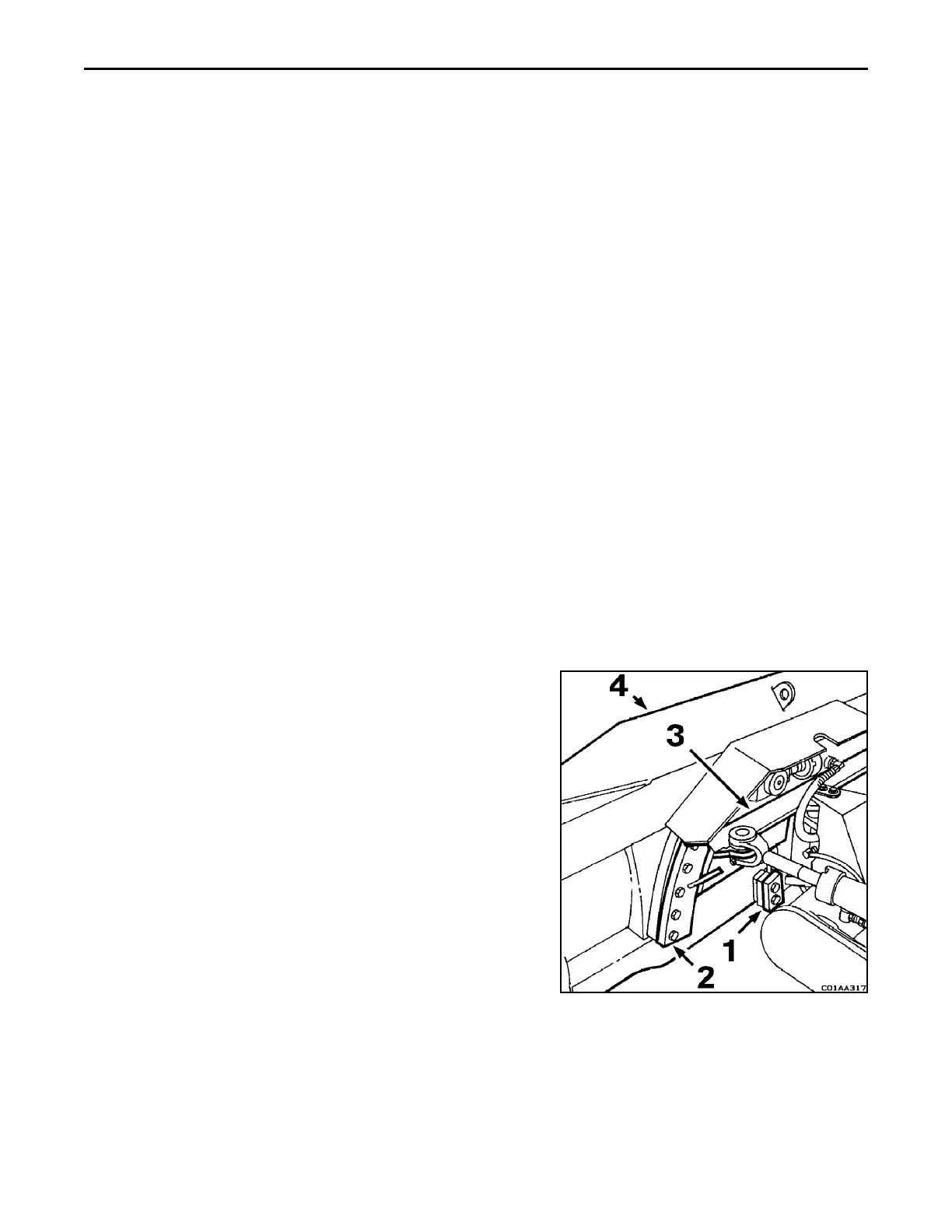
ADJUSTING
Periodically or as required the lower (1) and upper (2) shims (both
sides) may have to be removed to take up wear between the angling
frame (3) and the blade (4). The gap between the angling frame and
blade should not exceed 3 mm (0.12 in) minimum gap.
The lower shim pack is to consist of no less than 1 shim and no
more than 6 shims. The upper shim pack is to consist of no less than
2 shim and no more than 7 shims. The gap should permit free
movement between the angling frame and blade without any
binding.
 Loading...


