EQUIPMENT PUMP PUMPS
10A - 19
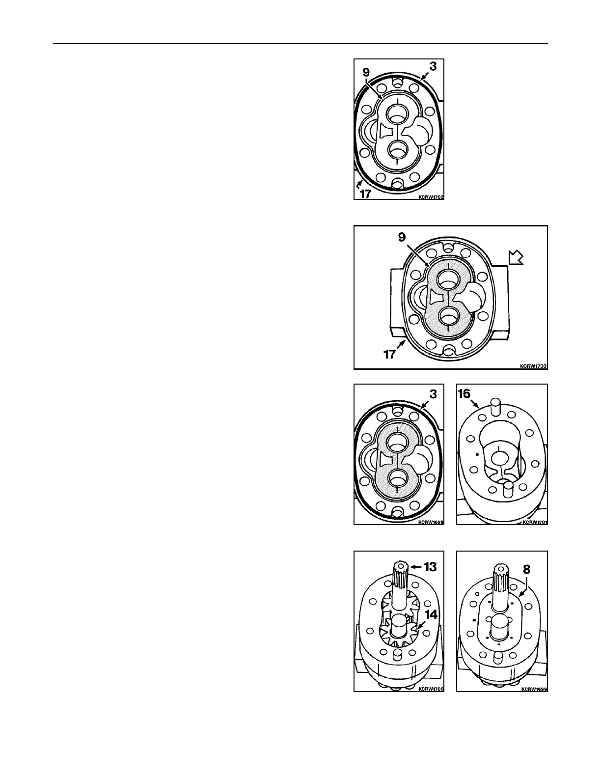
14. Remove thrust plate (9) and section o-ring (3) from back plate
(17).
INSPECTION
1. Tie bolts (10 and 11) and seal repair kit (1 through 9) are only
serviced parts. If any other part other than these need replace-
ment, replace complete pump.
2. Clean all parts and dry thoroughly with compressed air. Inspect
edges and faces of gears for scoring or roughness. If possible,
remove with Carborundum stone. Inspect shaft and bushings
for excessive wear. Inspect remaining parts for wear, cracks and
breakage.
REASSEMBLY
REMARK
Callouts from exploded and cross section views correspond with
callouts in following steps.
REMARK
When reassembling pump, absolute cleanliness is a must to
prevent premature failure. Lubricate all parts liberally as they are
assembled with clean oil.
1. Install thrust plate (9), bronze side up, with cut out towards
suction port, large port, to back plate (17).
2. Coat section o-ring (3) with amber grease and install to groove
in back plate.
3. Aligning match marks, install housing (16) to back plate.
4. Install drive (13) and driven (14) gears.
5. Install diaphragm (8), bronze face down on gears.
 Loading...


