RIPPER CYLINDERS
10C - 13
RIPPER CYLINDER REMOVAL
1. Retainer Ring 15. Lock Nut
2. Cylinder Gland 16. Rod Bushing
3. Rod Wiper
q
4. Rod Seal
q
5. Buffer Ring
q
6. O-Ring
q
7. Back Up Ring
q
8. O-Ring
q
9. Wear Ring
q
10. Seal Ring
q
11. O-Ring
q
12. Wear Ring
q
13. O-Ring
q
14. Cylinder Piston
17. Cylinder Rod
18. Barrel Bushing
19. Cylinder Barrel
q
- Part of Cylinder Seal Kit
SPECIFICATIONS
Bore and Stroke ........................................................... 76.2x172.72 mm (3x6.8 in)
Weights ............................................................................31 kg (69 lbs)
Torques - Piston Lock Nut ............................................ 610 to 678 NCm (450 to 500 lbf ft)
Seal Test Pressure .............................................................. 2750 kPa (400 psi)
Rod End Travel .............................................. Not to Exceed 1 mm (0.039 in) Per Minute
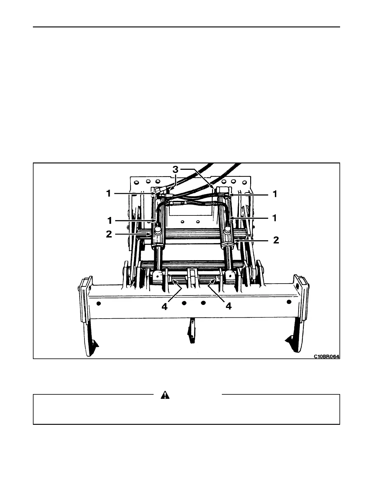
REMOVAL
1. Ripper Cylinder Hoses 3. Front Mounting Pin
2. Ripper Cylinder 4. Rear Mounting Pin
WARNING
Park machine on level ground, and stop engine, lower the blade and all attachments to the ground, lock
the transmission shift lever in neutral, apply the brake pedal lock, and turn off electrical system master
switch.
1. Operate equipment control lever to relieve any pressure in system. Disconnect and cap hoses (1) at cylinder (2).
Drain into a suitable container. Attach hoist and sling to cylinder. Remove front (3) and rear (4) mounting pins from
cylinder and remove.
 Loading...


