TRANSMISSION TRANSMISSION/STEERING VALVE
7C - 152
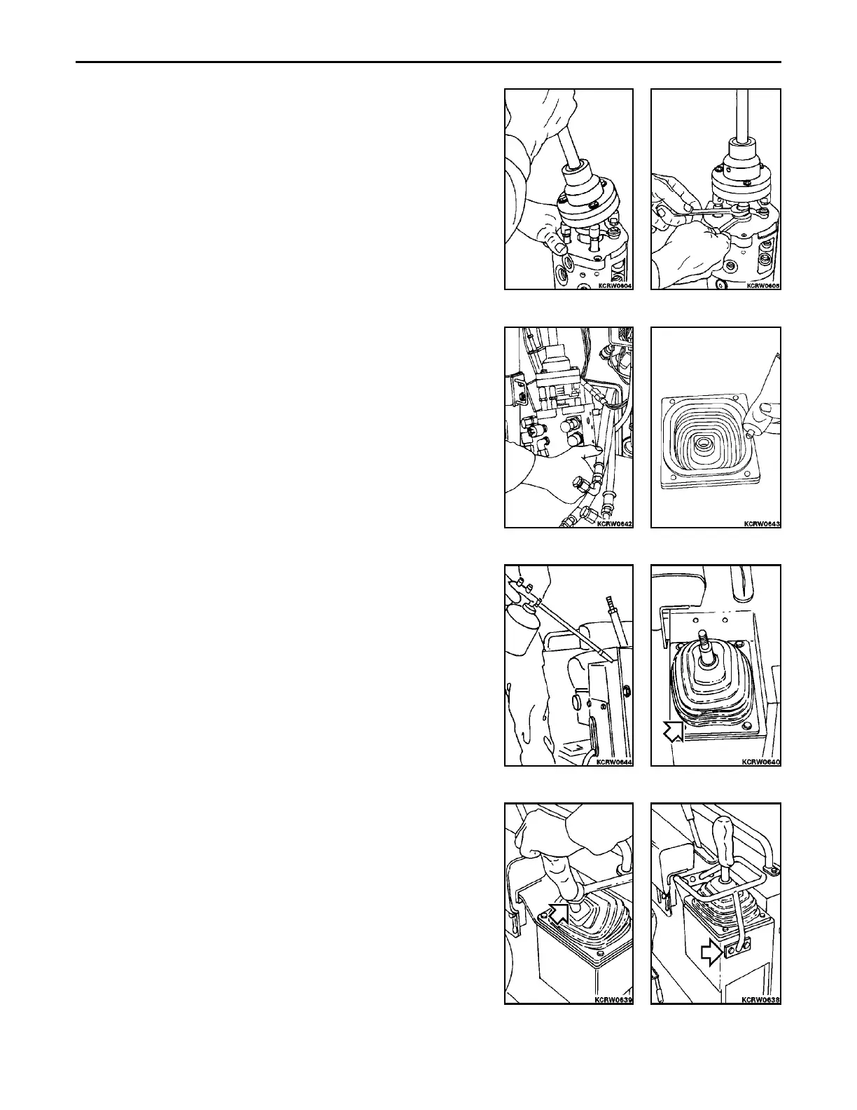
3. Move motion lever fully in all directions to seat range selector
spool against needle bearing. Recheck for free play between
cam ring and rocker ends and correct as necessary.
4. Tighten jam nuts to spool rocker ends.
INSTALLATION
1. Apply Loctite #515 to valve mounting surface. Using large flat
washer on valve lever, lift valve, tilting forward to clear reed
switch magnet, into position and secure with mounting hard-
ware.
2. Apply clear RTV sealant to underside boot all around to fashion
a water tight joint.
3. Apply corrosion inhibiter to inside of valve mounting cavity.
4. Install boot with clamp and plate and secure with hardware.
REMARK
Lever portion of boot incorporates an o-ring, be careful not to cut
or damage during installation.
5. Install handle to desired position and secure with jam nut.
6. Install feathering handle and secure with hardware.
 Loading...


