UNDERCARRIAGE WEAR LIMIT CHECKS
14 - 8
GENERAL
Track components have a certain dimension when new. As wear occurs
dimensions will decrease (or increase in case of track pitch and front idler
flange height) until a decision must be made whether to rebuild or recondition
components, replace them or run them to destruction. For each component
or condition, five different dimensions are given. 100% is dimension of
component when new. 075%, 050% and 025% indicate % of wear remaining
before a maintenance action should be taken. 000% is point at which either
maintenance must take place or components run to destruction. Before
inspecting, chain tension on both sides must be tightened. To do this, blocks
of wood or metal should be placed in sprocket tooth under chain. Machine
should then be moved backward so sprocket can grab block and tighten
chain. This pulls chain tight off top idler.
REMARK
Tools used to measure undercarriage components are included in Track
Specialist Kit 637985C91.
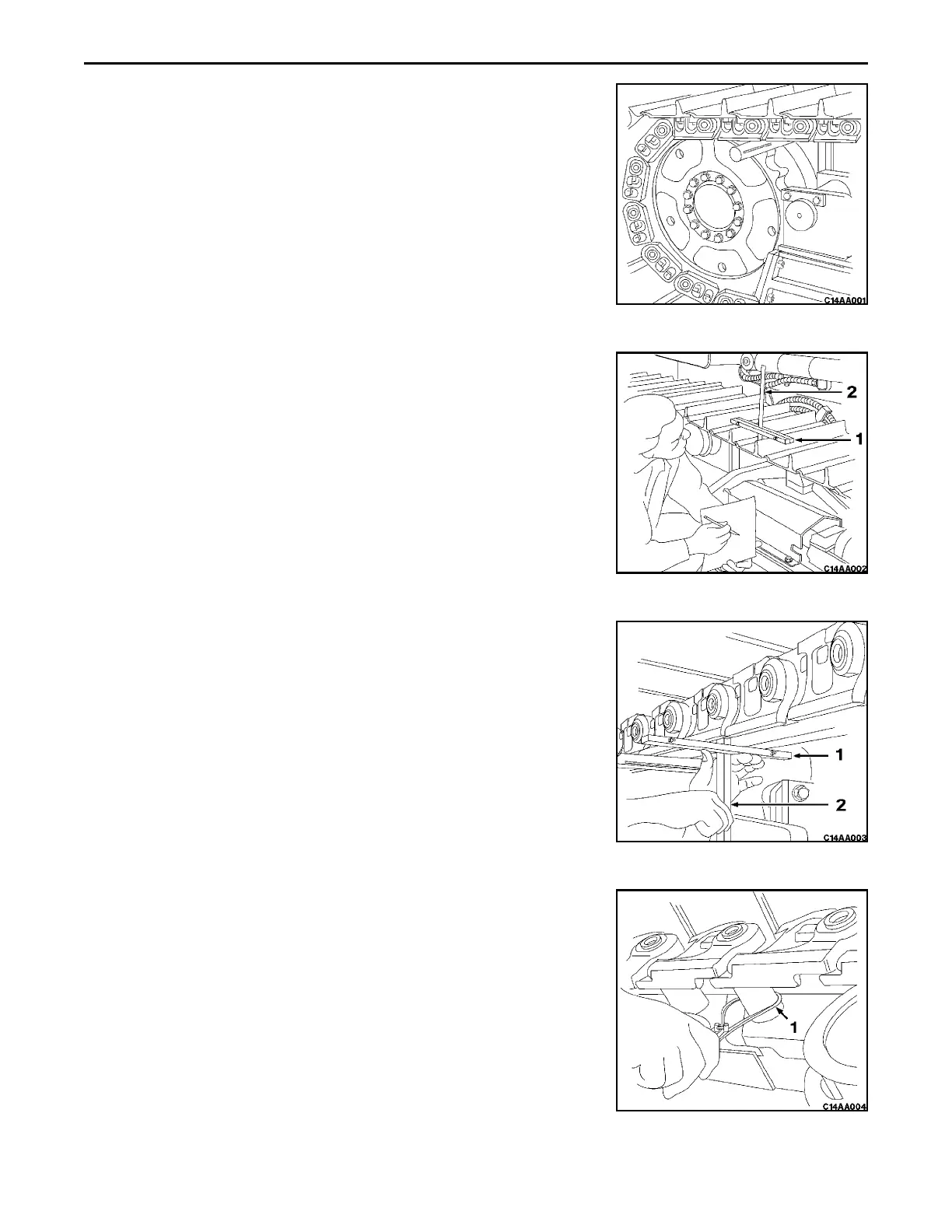
TRACK SHOE GROUSER HEIGHT
Clean off all materials on shoe plate and grouser tops. Lay squeeze bar (2)
across grousers approximately ¼ of way in from end of shoe. Insert 305 mm
(12 in) scale (1) in squeeze bar so that scale is against top of track plate and
take a reading. Measure two or more shoes to get an average. Refer to
SPECIFICATIONS.
LINK HEIGHT
Clean out all materials between links. Place squeeze bar (1) across center
of links. Insert 305 mm (12 in) scale (2) in squeeze bar so that scale is
against bottom of track shoe plate and take a reading. Measure two or more
place along chain to get an average. Refer to SPECIFICATIONS.
BUSHING OUTSIDE DIAMETER
Close 102 mm (4 in) outside caliper (1) around bushing with a minimum
amount of drag, making certain that one of caliper tips is positioned in
forward drive side wear area. Slide caliper off bushing and measure distance
between caliper tips using 305 mm (12 in) scale. Repeat on reverse drive
side wear area. Measure two or more bushings to get an average. Refer to
SPECIFICATIONS.
REMARK
Whichever wear is greater, forward or reverse, determines percentage of
wear remaining.
 Loading...


