TRANSMISSION DRIVE SHAFT
7C - 156
SERVICE
WARNING
Be sure blade and any rear mounted equipment has been
lowered to the ground or on suitable blocking. Turn the
master switch to the off position and remove key.
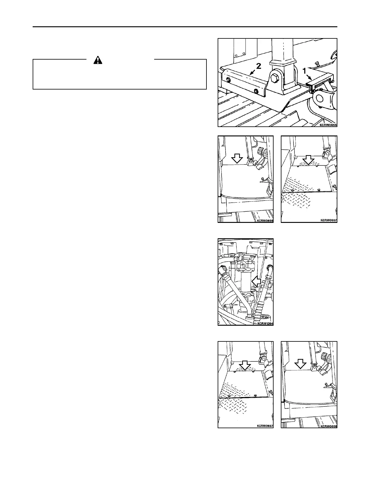
1. Remove front (1) and side (2) floor mat retainer angles from
each side of machine.
2. Remove floor mat.
3. Remove floor plate.
4. Disconnect spider at torque converter. Slide shaft back into
transmission, pull up to clear converter yoke and remove from
machine. Check condition of shaft parts and replace as neces-
sary. Check oil seal at transmission input shaft and replace if
necessary. If seal is replaced install new seal flush with housing.
5. Position drive shaft yoke to transmission input shaft and slide in
being careful not to damage oil seal. Align front spider to
converter yoke and secure with bolts. Torque bolts, D32E-1,
D32P-1, D38E-1 or D38P-1 to 33 NCm (24 lbf ft) or D39E-1 or
D39P-1 to 57 NCm (42 lbf ft).
6. Install operators compartment floor plate. Torque bolts to 38
NCm (28 lbf ft) ±10%.
7. Install floor mat.
 Loading...


