BRAKE AND DECELERATOR PEDAL BRAKES
4 - 5
REMOVAL
WARNING
Be sure blade and any rear mounted equipment has been lowered
to the ground or on suitable blocking. Turn the master switch to the
off position and remove key or remove one of the cables from the
master switch to prevent accidental starting.
WARNING!
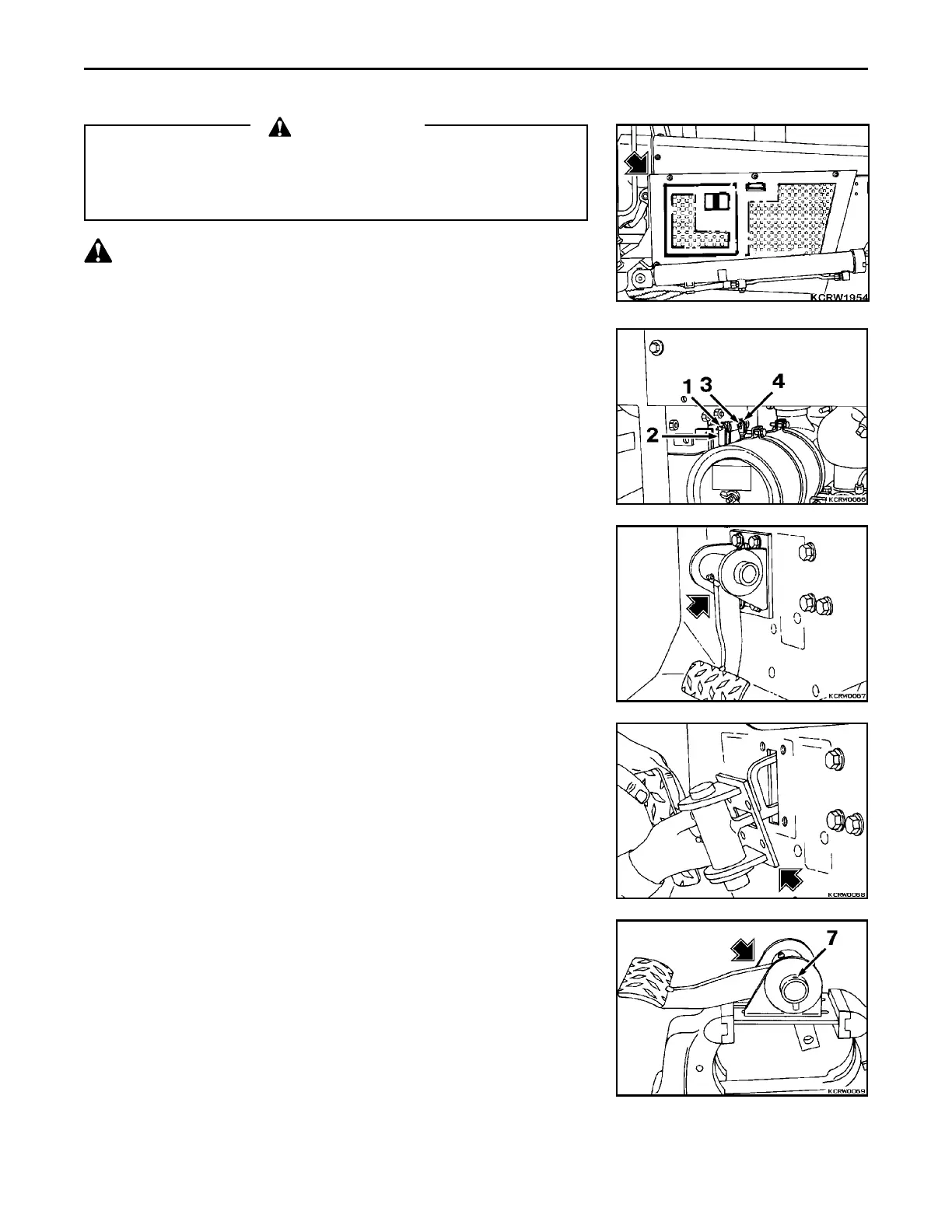
1. Remove engine right side door.
2. Remove cotter and clevis pins (1) from brake rod (2) and release from
pedal. Remove cotter and clevis pins (3) from decelerator over travel rod
(4) and release from pedal.
3. Remove hardware securing pedal and bracket to dashboard.
4. Rotate pedal and bracket 90E sideways and remove from dashboard.
SERVICE
REMARK
Callouts from exploded view correspond with callouts in following steps.
1. Position assembly in vise. Drive roll pin (7) from mounting bracket and
shaft.
 Loading...


