BLADE TILT SECTION CONTROL VALVE
10B - 31
DISASSEMBLY
REMARK
Callouts from exploded and cross section views correspond with
callouts in following steps.
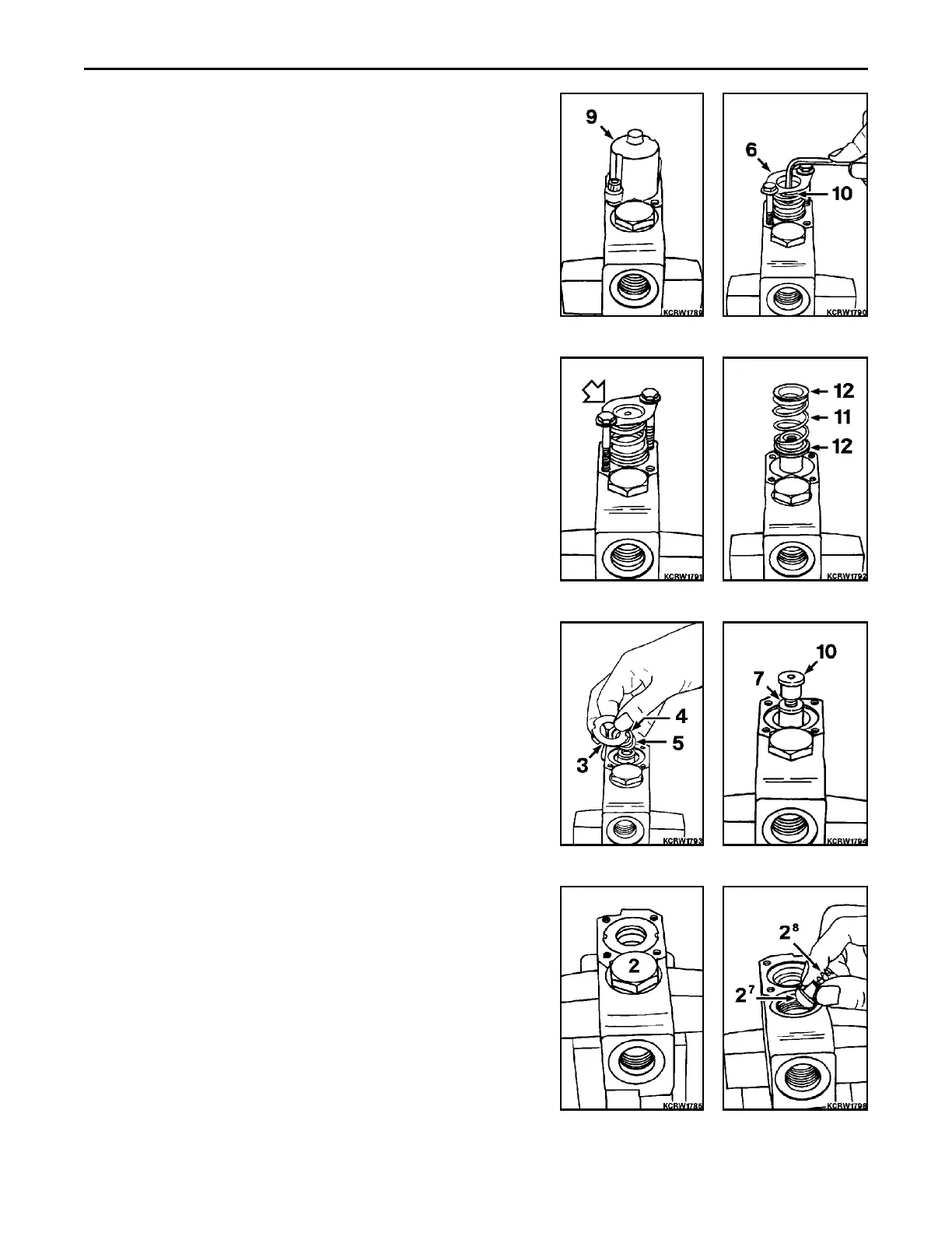
1. Position blade tilt section in vise. Remove hardware and spool
positioner housing (9).
2. Install shipping/retainer plate, 1299240H1, (6) over spool spring
retainer and secure with bolts. Draw down evenly on bolts until
spool collar (10) is free, then remove.
3. Slowly and evenly let off bolts until all tension on spring is
relieved.
4. Remove spool retainers (11) and centering spring (12).
5. Remove seal retainer (3), back up seal (4) and o-ring seal (5) at
each end of spool bore.
6. Insert spool collar (10) to spool (7) and remove.
7. Remove load check valve (2) from valve body. Separate check
poppet (2/7) and poppet spring (2/8) from body (2/6). Remove
and discard all software (2/1 through 2/6). Replace with new.
REASSEMBLY
REMARK
Callouts from exploded and cross section views correspond with
callouts in following steps.
1. Install load check valve (2) at each spool end as follows.
Install check poppet (2/7) and poppet spring (2/8) into valve
bore.
 Loading...


