GENERAL DRIVE TRAIN
7 - 5
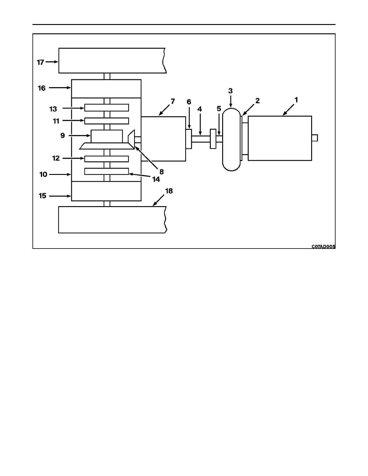
DRIVE TRAIN COMPONENTS
1. Engine 7. Transmission 13. Left Brake Disc
2. Flex Plate 8. Output Shaft and Pinion 14. Right Brake Disc
3. Torque Converter 9. Bevel Gear Carrier 15. Right Sprocket Drive
4. Drive Shaft 10. Rear Main Frame 16. Left Sprocket Drive
5. Output Flange 11. Left Clutch Disc 17. Left Track
6. Transmission Input Flange 12. Right Clutch Disc 18. Right Track
DESCRIPTION
Power from the engine (1) is transmitted through a flex plate (2) to the torque converter (3). A drive shaft (4) couples
the output flange (5) of the torque converter with the input flange (6) of the transmission.
When the transmission is engaged, power is transmitted from the output shaft and pinion gear (8) to the bevel gear
carrier (9) in the rear frame (10).
OPERATION
The rear main frame is the common oil reservoir for the torque converter, transmission and steering drive. When the
engine is running, oil is drawn from bottom of the rear main frame, through suction strainer and on to the charge pump
(front section). The charge pump delivers oil flow through the pressure filter to the M port of the main pressure regulator
valve. For a more complete description and operation of the main pressure regulator valve, refer to Section 7C. The
charge pump flow is also teed off the line to the main pressure regulator valve to feed the neutral start valve and
transmission/steering valve. For a complete description of components, refer to Section 7C.
 Loading...


