7C - 111
INSTALLATION TRANSMISSION
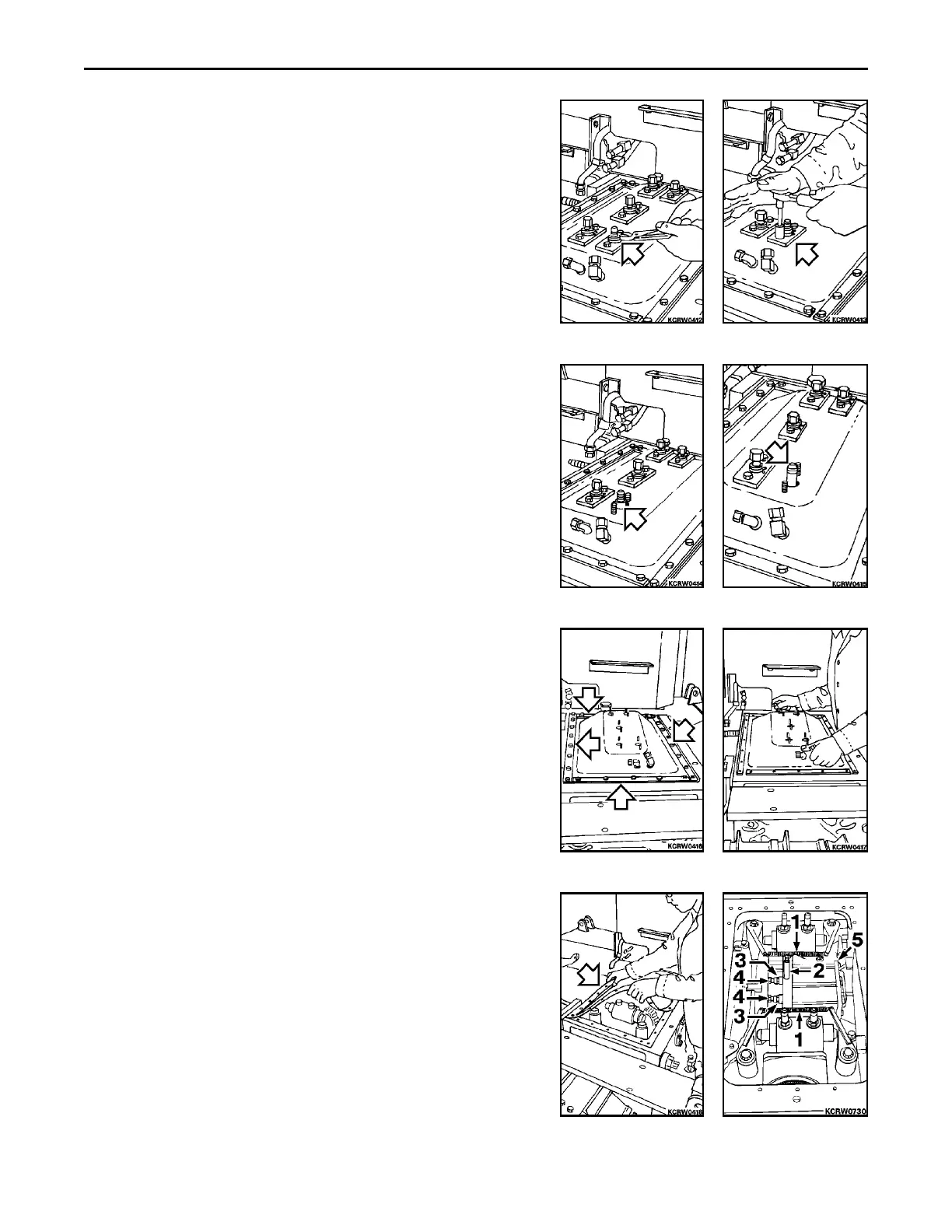
1. Remove caps from fittings. Using lock ring pliers, remove
retaining ring.
2. Remove hardware and seal flange.
3. Remove connector boot.
4. Remove long connector from cylinder. Repeat Steps 1 through
4 for remaining four fittings.
5. Remove hardware and side, front and back stiffeners.
6. Remove rear frame cover.
7. Remove and discard rear frame cover gasket. Replace gasket
with new.
8. Remove arm return springs (1). Connect a 2070 kPa (300 psi)
power source to connector (2) to retract actuator rods. Loosen
lock nuts (3) and turn in adjusting bolts (4). Remove hardware,
then remove brake cylinder (5) from base plates.
REMARK
For cylinder service, refer to Section 7E.
 Loading...


